EGRO 55 SERIES TECHNICAL MANUAL EGRO 55 SERIES TECHNICAL MANUAL © Copyright 2008.
This page is intentionally left blank.
TABLE OF CONTENTS: SECTION 1: INTRODUCTION SECTION 2: INSTALLATION SECTION 3: PROGRAMMING SECTION 4: ELECTRICAL SECTION 5: HYDRAULIC SECTION 6: ADJUSTMENTS AND MAINTENANCE © Copyright 2008.
This page is intentionally left blank.
EGRO 55 SERIES TECHNICAL MANUAL SECTION 1: INTRODUCTION AND OVERVIEW TABLE OF CONTENTS: SECTION 1 Page 1.1 MACHINE OVERVIEW.................................................................................................................. 2 - 3 1.1a. Model 5511- identifies parts of machine................................................................................................. 2 1.1b Model 5513 - identifies parts of the machine and the Model KS Fridge.................................................
This page is intentionally left blank.
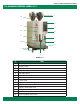
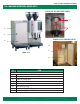
EGRO 55 SERIES TECHNICAL MANUAL 1.1a MACHINE OVERVIEW: MODEL 5511 1 14 2 13 3 12 4 11 5 10 6 7 9 8 MODEL 5511 # 1 2 3 4 5 6 7 8 9 10 11 12 13 14 © Copyright 2008. Rancilio North America ITEM Bean Hoppers (capacity 2.
EGRO 55 SERIES TECHNICAL MANUAL 1.1b. MACHINE OVERVIEW: MODEL 5513 CLOSE-UP OF MACHINE PARTS 18 19 15 16 CLOSE-UP OF FRIDGE PARTS 17 20 21 MODEL 5513 22 # ITEM Model 5513 includes items 1-14 as described on the previous page PLUS the following items... 15 16 17 18 19 20 21 22 Above the counter Model KS refrigerator Model KS fridge door latch Model KS fridge door AFV (Air Foam Valve) Frother heads Milk pump housing Hoses to Milk gallon Standard US gallon of Milk © Copyright 2008.
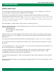
EGRO 55 SERIES TECHNICAL MANUAL 1.2 SAFETY PRECAUTIONS GENERAL SAFETY RULES Do not leave packing materials (plastic bags, expanded polystyrene, nails, cardboard, etc.) within the reach of children, as these items are a potential source of danger. Verify that the electrical data of the machine corresponds with the electrical supply network before connecting the machine to the power source. PLEASE NOTE: Egro Model 55 series machines require 208V 30amp main power supply.
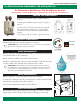
EGRO 55 SERIES TECHNICAL MANUAL 1.3a PRE-INSTALLATION REQUIREMENTS FOR EGRO MODEL 5511 ALL REQUIREMENTS ARE NECESSARY FOR EACH MACHINE INSTALLED (TWO MACHINES = DOUBLE COUNTER SPACE, 2 ELECTRICAL LINES, 2 WATER LINES, 2 DRAINS ETC...) COUNTER TOP REQUIREMENTS Counter must be able to support 150lbs (300lbs for 2 machines). Counter space available must be 18”W x 261/2”D x 39”H*. Counter needs a 31/2 inch access hole for electrical lines, water, and/or drain hoses.
EGRO 55 SERIES TECHNICAL MANUAL 1.3b PRE-INSTALLATION REQUIREMENTS FOR EGRO MODEL 5513 WITH A MODEL KS FRIDGE ALL REQUIREMENTS ARE NECESSARY FOR EACH MACHINE INSTALLED (TWO MACHINES = DOUBLE COUNTER SPACE, 2 ELECTRICAL LINES, 2 WATER LINES, 2 DRAINS ETC...) COUNTER TOP REQUIREMENTS Counter must be able to support 200lbs. Counter space available must be 30”W x 261/2”D x 39”H*. Counter needs a 31/2 inch access hole for electrical lines, water, and/or drain hoses.
EGRO 55 SERIES TECHNICAL MANUAL SECTION 2: INSTALLATION TABLE OF CONTENTS: SECTION 2 Page 2.1 INSTALLATION OVERVIEW.............................................................................................................. 2 2.2 - 2.12 STEP BY STEP INSTRUCTIONS FOR INSTALLATION .............................................................. 3 - 12 2.2 2.3 2.4 2.5 Install feet on machine and KS fridge (for model 5513)................................................................................
This page is intentionally left blank.
EGRO 55 SERIES TECHNICAL MANUAL 2.
EGRO 55 SERIES TECHNICAL MANUAL 2.2 - 2.12 INSTALLATION INSTRUCTIONS: STEP BY STEP GUIDE 2.2 INSTALL FEET ON MACHINE AND KS FRIDGE (WITH MODEL 5513) The Egro 55 Series machine comes with riser feet to provide adequate space to easily clean beneath the machine. The Egro Model 5511 comes with 4 fee, and the 5513 with a KS Fridge comes with 8 feet, four for the machine and four for the fridge. PLEASE NOTE: It is recommended that two people perform that steps below.
EGRO 55 SERIES TECHNICAL MANUAL 2.2 - 2.12 INSTALLATION INSTRUCTIONS: STEP BY STEP GUIDE 2.4 CONNECT WATER LINE TO MACHINE PLEASE NOTE: You will need a 3/8” NPT to 3/8” BSPT fitting to connect the incoming water supply to the water connection of the Egro 55 series machine. The incoming water supply line, to the machine should be a male 3/8” NPT fitting. The water connection on the Egro 55 machine is 3/8” BSPT. WARNING: A water softener/filter for incoming water supply is REQUIRED.
EGRO 55 SERIES TECHNICAL MANUAL 2.2 - 2.12 INSTALLATION INSTRUCTIONS: STEP BY STEP GUIDE 2.5A CONNECT THE DRAIN LINE TO THE HOUSE DRAIN (MODEL 5511) right side panel screws STEPS TO CONNECT THE EGRO MODEL 5511 ATTACHING THE SILICON HOSE 1. Remove the right side panel of the machine, by removing the two screws on top of the machine. Lift the right-side panel straight up to remove it. 2. Locate the brew valve solenoid on the back-right side of the machine, beneath the hot water boiler (smaller boiler).
EGRO 55 SERIES TECHNICAL MANUAL 2.2 - 2.12 INSTALLATION INSTRUCTIONS: STEP BY STEP GUIDE 2.5B CONNECT THE DRAIN LINE TO THE HOUSE DRAIN ON THE MODEL 5513 FOLLOW STEPS 1 - 9 AS DESCRIBED FOR INSTALLING THE DRAIN HOSE OF A MODEL 5511. PLUS FOLLOWING THESE STEPS... CONNECTING THE DRAIN HOSE OF THE KS FRIDGE 12. Locate the drain hose provided with the KS fridge 13. Attach the hose to outlet on the underneath of the drip on the KS fridge and route the drain hose to the floor drain. 2.
EGRO 55 SERIES TECHNICAL MANUAL 2.2 - 2.12 INSTALLATION INSTRUCTIONS: STEP BY STEP GUIDE 2.6 CONNECT THE KS FRIDGE TO THE MACHINE (MODEL 5513 ONLY) - CONTINUED CONNECT MILK RINSING LINE 7. Locate the milk rinsing line in the fridge. This is the clear shorter teflon hose. Route it through the hole on the right side panel of the fridge and through the hole on the left side panel of the machine. Connect it to the hose with quick connect. CONNECT FRIDGE WIRING 8. Locate the 3 wires need for the fridge.
EGRO 55 SERIES TECHNICAL MANUAL 2.2 - 2.12 INSTALLATION INSTRUCTIONS: STEP BY STEP GUIDE 2.8 CONNECT THE MACHINE TO POWER SUPPLY PLEASE NOTE: The Egro 55 series machine requires a NEMA L6-30R receptacle. The optimal voltage supply is 230V. An acceptable range of voltage is 208V - 250V. If the power supply does not produce 208V of steady voltage, a voltage booster is required. If the power is above 250V, a buck’n boost transformer may be required. The Egro machines do not use a neutral line.
EGRO 55 SERIES TECHNICAL MANUAL 2.2 - 2.12 INSTALLATION INSTRUCTIONS: STEP BY STEP GUIDE 2.10 DE-PRESSURIZE STEAM BOILER PLEASE NOTE: This step is very important because the steam boiler MUST depressurize before it can function correctly. FOR EGRO 55 SERIES MACHINES WITH THE TS WAND FOLLOW THESE STEPS: 1. After turning on machine, press the TS wand activation button. 2. After steam begins to exit the wand, press the TS wand activation button again to stop the flow of steam.
EGRO 55 SERIES TECHNICAL MANUAL 2.2 - 2.12 INSTALLATION INSTRUCTIONS: STEP BY STEP GUIDE 2.11 ADJUST GRINDERS -- CONTINUED STEPS FOR ADJUSTING GRINDER WITH AN INTERNAL GRINDER ADJUSTMENTS INSTALLED 1. Using a Phillips head screwdriver remove the screw which locks the door and swing the door open. WARNING: do not loose this screw. 1 2. Choose the grinder which needs to be adjusted. Turn the knob 1/2 turn to 1 full turn roation, close the door and test a product.
EGRO 55 SERIES TECHNICAL MANUAL 2.2 - 2.12 INSTALLATION INSTRUCTIONS: STEP BY STEP GUIDE 2.12 CALIBRATE MACHINE TO BEANS (DIALING IN 10 GRAMS) - CONTINUED Product Total X Products... X Config1... X Config2... X Service... Grinders... GL Sec/10Gr GR Sec/10Gr Grinder L test? Left Grinder, grinding time in seconds to produce 10 grams of coffee. TIP: First, set your grinder to produce the coarseness of grind you prefer. Second: perform the Grinder tests as described below.
EGRO 55 SERIES TECHNICAL MANUAL 2.2 - 2.12 INSTALLATION INSTRUCTIONS: STEP BY STEP GUIDE 2.12 CALIBRATE MACHINE TO BEANS (DIALING IN 10 GRAMS) - CONTINUED 8.3 If the weight is not 10 grams, then scroll back (using the number 3 button) until the screen reads, GL Sec/10Gr. 8.3 GL Sec/10Gr 8.4 Press ENTER or button 1 to make adjustments to the grinding time of the left grinder. 8.5 Use the + and - (buttons 7 and 9) to make adjustments to the grind time.
EGRO 55 SERIES TECHNICAL MANUAL SECTION 3: PROGRAMMING TABLE OF CONTENTS: SECTION 3 Page 3.1 INTRODUCTION TO PROGRAMMING............................................................................................ 2 - 6 3.1a Keypad definitions................................................................................................................................ 2 - 3 3.1b Changing operating mode: how to enter programming mode..................................................................... 4 3.
This page is intentionally left blank.
EGRO 55 SERIES TECHNICAL MANUAL 3.1 INTRODUCTION TO PROGRAMMING: 3.1a. KEY PAD DEFINITIONS All programming of the Egro equipment is done from the keypad. The buttons are labeled with small gray numbers. These numbers represent the corresponding product number. PLEASE NOTE: On the standard 5511 machine the second row of numbers (product numbers 2, 4, 6 and 8) are located to the right and are not labeled by black push buttons, however they are labeled by small gray numbers.
EGRO 55 SERIES TECHNICAL MANUAL 3.1a. KEY PAD DEFINITIONS Each product button on the key pad represents a type of product in the programming. For example, button number 1 contains all the settings for the single espresso. Buttons 0, 1, 3, 5, 7 and 9 (all the buttons on the left side of the key pad) also have functional programming abilities such as Enter, Esc, Scroll up, scroll back, scroll forward, increase by 1 and decrease by 1). Please see the photo diagram below for further details.
EGRO 55 SERIES TECHNICAL MANUAL 3.1b. CHANGING OPERATING MODE: HOW TO ENTER PROGRAMMING MODE 1 OPERATING MODES ‘Mode’ refers to a specific style of operation of the machine. The machine operates in a different manner in each mode or, alternatively, other operations are carried out.
3.1c. PROGRAMMING MENU OVERVIEW Product Total P_ PT Clear? # X X Products... Config1... P_Price P_Name Grinders... P_Type P_Reg. Nr. GL Sec/10Gr P_FM Pulses P_Bypass GR Sec/10Gr P_Gram Grinder L test? P_Cap Time Grinder R test? P_Foam Ref-Temp. CB P_Cap Delay Capp Corr P_Cap. Product Prerinse P_Cof. Delay Press.Reg. P_Pre-Inf Grounds Value P_PI Time Presel. Mode1 P_PI Pause Presel. Mode2 P_Pressure W_Control P_Time P1 Turns P_Cof.
3.1c. PROGRAMMING MENU OVERVIEW -- CONTINUED X Config2... X Language PT-Eraser Decimal Point Auto-Steam Periph. Type iButton Foam Card System M_Value Service... Last Errors Error Cycles P-Serv iButton Milk Max cycles iSteamCorrFct CLR P-Serv Steam Boiler Ref. Temp. AS W-Serv Power Fahrenheit Watertank Max. Flowm Tea/Steam Power Version CLR W-Serv Save to Card? C-Cleanings Load Card? M-Cleanings Load Defaults CLR Error Price=> CCI Monitor... Shift Valve test.. Choko Heater test.
3.2 CUSTOMER MONITORING MODE -- OPERATING MODE 3 EGRO 55 SERIES TECHNICAL MANUAL The Product total menu allows customers to easily monitor the total number of products that have been produced using the Egro 55 series machine. 1. Change the operating mode of the machine to, MODE 3 (Customer Monitoring mode or Product Total menu) 1.1 Insert key turn to the right. 1.2 Press number 3 button on the key pad. PROGRAMING MENU DIAGRAM Product Total X P_ # Products... X Config1... X Config2...
EGRO 55 SERIES TECHNICAL MANUAL 3.3 PRODUCT MENU: HOW TO SET DRINK PARAMETERS IN PROGRAMMING MODE The Products menu allows for the custom programming of each drink product individually. Every setting that can have an influence on the taste, quality and consistency of the drink may be fine-tuned using the Products menu. Each product button on the key pad represents a type of product in the programming. For example, on a Model 5511 button number 1 typically contains all the settings for the single espresso.
EGRO 55 SERIES TECHNICAL MANUAL 3.3 PRODUCT MENU: HOW TO SET DRINK PARAMETERS IN PROGRAMMING MODE DESCRIPTION OF PRODUCT SETTINGS/PARAMETERS: --- CONTINUED PROGRAMING MENU DIAGRAM Product Total X Products... X Config1... X Config2... X Service... This setting determines the quantity of steamed milk that is delivered to produce cappuccinos and lattes.
EGRO 55 SERIES TECHNICAL MANUAL 3.3 PRODUCT MENU: HOW TO SET DRINK PARAMETERS IN PROGRAMMING MODE PROGRAMING MENU DIAGRAM Product Total P_Time X Products... X Config1... X Config2... X Service... NOT RECOMMENDED, MAY CAUSE ERRORS. Brewing time control or auto-adjust tamping control, modifies the tamping pressure if the brewing time does not correspond to this set value. (Only valid if Pressreg., in Config1 menu is turned ON (=1).) P_Cof.
EGRO 55 SERIES TECHNICAL MANUAL 3.3 PRODUCT MENU: PRODUCT NAME LIST Following is list of settings that correspond to the product name that will be displayed on the machine’s display screen when the user presses the product button. NUMBER PRODUCT NAME NUMBER PRODUCT NAME 0 Empty 38 Americano 1 Ristretto 39 2x Americano 2 Espresso 40 Caffe’ Lungo 3 2x Ristretto 41 2x Caffe’ Lungo 4 2x Espresso 42 Decaf. s. Capp. 5 Coffee 43 Decaf m. Capp. 6 2x Coffee 44 Decaf. l Capp.
EGRO 55 SERIES TECHNICAL MANUAL 3.4 CONFIG 1 MENU Config 1 Menu contains parameters for making adjustments to the machine that do not effect the specific drink parameters. Product Total X Products... X Config1... X Config2... X Service... Grinders... GL Sec/10Gr GR Sec/10Gr Grinder L test? Left Grinder, grinding time in seconds to produce 10 grams of coffee. TIP: First: set your grinder to produce the coarseness of grind you prefer. Second: perform the Grinder tests as described below.
EGRO 55 SERIES TECHNICAL MANUAL 3.4 CONFIG 1 MENU Config 1 Menu contains parameters for making adjustments to the machine that do not effect the specific drink parameters. Product Total Presel. Mode1 Presel. Mode2 W_Control X Products... X Config1... X Config2... X Service... Specifies the total number of drinks that can be queued or preselected in modes 1 and 2. PLEASE NOTE: 1 = No drink queuing possible. (Options 1 - 16) In a self service application this parameter must always be set to =1.
EGRO 55 SERIES TECHNICAL MANUAL 3.5 CONFIG 2 MENU Config 2 Menu contains parameters for making adjustments to the machine that do not effect the specific drink parameters. Product Total X Products... X Config1... X Config2... X Service... Language Specifies which language. (Options German, English, French, and Japanese) Decimal Point NOT USED IN USA. Specifies the number of spaces after the decimal point in drink places. 0 = no spaces 1 = Two spaces Periph. Type NOT TYPICALLY USED IN USA.
EGRO 55 SERIES TECHNICAL MANUAL 3.5 CONFIG 2 MENU Config 2 Menu contains parameters for making adjustments to the machine that do not effect the specific drink parameters. Product Total X Products... X Config1... X Config2... X Service... Load Card? Uploads the settings from a service card to the Products, Config1, and Config2 menus of the machine. ONLY VALID WITH A CARD READER ATTACHED TO THE MACHINE.
EGRO 55 SERIES TECHNICAL MANUAL 3.5 CONFIG 2 MENU Config 2 Menu contains parameters for making adjustments to the machine that do not effect the specific drink parameters. Product Total X Products... X Config1... X Config2... X Service... C-Request Cleaning request function. Use this feature to set a cleaning alert after a specified number of drinks have been produced. The alert will remain on the screen until the cleaning has been carried out.
EGRO 55 SERIES TECHNICAL MANUAL 3.5 CONFIG 2 MENU Config 2 Menu contains parameters for making adjustments to the machine that do not effect the specific drink parameters. Product Total X Products... X Config1... X Config2... X Service... ISTEAM SETTINGS: ONLY VALID WHEN ISTEAM WAND IS PRESENT iButton Milk Temperature E-degree iButton Milk: This submenu contains the programming for the temperature and emulsion levels of the latte button or right side button on the iSteam wand.
EGRO 55 SERIES TECHNICAL MANUAL 3.6 SERVICE MENU Service menu is for maintenance and diagnostics. It contains information as well as component diagnostic tests. Product Total Last Errors X Products... X Config1... X X Config2... Service... Submenu which contains last errors machine encountered. E061 Displays the last 64 error messages that the machine encountered, and how many cycles the machine had performed when the error occurred.
EGRO 55 SERIES TECHNICAL MANUAL 3.6 SERVICE MENU Service menu is for maintenance and diagnostics. It contains information as well as component diagnostic tests. X Product Total Products... X Config1... X M-Cleanings Displays the number of milk cleanings since the last CLR P-Serv. CLR Error Clears the error history list. Service... X Config2... Contains a list of submenu tests that can be used to diagnose a problem. Monitor...
EGRO 55 SERIES TECHNICAL MANUAL 3.6 SERVICE MENU X Product Total Products... X Config1... X X Config2... Service... Contains a list of submenu tests that can be used to diagnose a problem. Monitor... AC Motor Test.. Function: Manually control the AC motor. Buttons used to select: + and Start/Stop: Use button #1 Status: 0 = ON 1 = OFF Display DC Motor Test.. or Level Test.. POS SW Test..
EGRO 55 SERIES TECHNICAL MANUAL 3.6 SERVICE MENU X Product Total Monitor... Products... X Config1... X X Config2... Service... Contains a list of submenu tests that can be used to diagnose a problem. Flow meter P1 (coffee) FlowM Test ADDITIONAL I/O Function: Check the flow-meter. Start/Stop: Use button #1 Display: Continuous display of FM signal. 100 FM-IMp. = approx. 0.5 dl. or 1.5oz Inputs... Component OUTPUTS... Function: Checks the 24V DC outputs.
EGRO 55 SERIES TECHNICAL MANUAL 3.7 GUIDE TO LED ON MAIN BOARD 3.7a LED LIST FOR R1 MAINBOARD LED 1 24 Volt (green continuous) LED 2 5 Volt (green continuous) LED 3 Run mode (green flashing) LED 4 Pump LED 5 Left grinder LED 6 Right grinder LED 7 Coffee boiler LED 8 Steam boiler LED 9 Brew valve LED 10 Tea valve LED 11 Steam filling valve LED 12 Cappuccino valve left LED 13 Cappuccino valve right LED 14 Spare LED 4 -14 Red (On = active) 3.
EGRO 55 SERIES TECHNICAL MANUAL 3.8 ERROR LIST 3.8 ERROR MESSAGES: When the machine has encounters a problem with one of it’s components it will give the end user an error message. Technicians can check the list of errors the machine has encountered and the number of cycles the machine had performed when the error occurred. SEE PAGE 18 OF THIS SECTION FOR MORE DETAILS ON HOW TO ACCESS THE ERROR LIST. NO. DESCRIPTION SOLUTION 1 Error in EEPROM Turn machine off, wait 30 seconds and turn on again.
EGRO 55 SERIES TECHNICAL MANUAL 3.8 ERROR LIST - CONTINUED 3.8 ERROR MESSAGES -continued NO. DESCRIPTION 93 Lower piston (P2) can not reach it’s maximum height. a. Check lower spindle motor (M8) - use monitor menu b. Revolution counter (S16) is faulty 94 Lower piston (P2) height has exceeded it’s maximum height during brewing. (Motor exceeded 100 revolutions) a. Check lower piston spindle motor - use monitor menu b. Revolution counter (S16) is faulty c.
EGRO 55 SERIES TECHNICAL MANUAL 3.9 PARAMETER QUICK INDEX PRODUCT SETTINGS PRODUCT SETTINGS: COFFEE PARAMETER P_Bypass DESCRIPTION MENU PAGE Products... 10 P_Coffee Source % of H2O delivered after brewing for Americanos Specifies which hopper supplies coffee Products... 10 P_FM Pulse Quantity of water delivered during brewing Products... 8 P_Grams Quantity of coffee used Products... 8 P_Pre-Inf Pre-infusion on or off Products... 9 P_PI_Pause Expansion time for pre-infusion Products.
EGRO 55 SERIES TECHNICAL MANUAL 3.9 PARAMETER QUICK INDEX MACHINE SETTINGS MACHINE SETTINGS: GRINDER CALIBRATION PARAMETER DESCRIPTION MENU PAGE Grind Time Left -- GL Sec/10Gr Defines grind time to grind 10 grams with left grinder Config 1... 12 Right -- GR Sec/10Gr Defines grind time to grind 10 grams with right grinder Config 1... 12 Grinder L test? Activates left grinder to calibrate Config 1... 12 Grinder R test? Activates right grinder to calibrate Config 1...
EGRO 55 SERIES TECHNICAL MANUAL 3.9 PARAMETER QUICK INDEX SENSORS, ALERTS, AND COUNTERS PARAMETER DESCRIPTION MENU PAGE C-Cleaning Displays number of times the coffee cleaning program has been run since last CLR-R-Serv Service... 18 CLR_Error Clears error history Service... 19 CLR_P_Serv Clears PM service counter Service... 18 CLR_W_Serv Clears water service counter Service... 18 C_Request Cleaning alert: Set # of cycles machine performs before giving a cleaning alert Config 2...
EGRO 55 SERIES TECHNICAL MANUAL 3.9 PARAMETER QUICK INDEX TECHNICIAN SUPPORT MENUS COMPONENT MONITORING PARAMETER DESCRIPTION MENU PAGE AC Motors Manually control the AC motors. Service/Monitor... 20 Additional IO Checks the 24V DC outputs. Service/Monitor... 21 Cool Down Cool down the machine for safe repairing. Flushes the boiler with cold water. Service/Monitor... 21 DC Motor Manually control the DC motors. Service/Monitor... 20 FlowM Test Manually activates the Flow meter.
EGRO 55 SERIES TECHNICAL MANUAL 3.10 ALPHABETICAL LIST OF PARAMETERS INDEX PARAMETER MENU AC Motors Service/Monitor PAGE 20 PARAMETER MENU PAGE PARAMETER MENU PAGE M_Cleanings Service 19 Power version Config 2 14 Config 1 12 Service/Monitor 21 Max_Cycles Service 18 Pre-Rinse AFV Config 1 13 Max.
EGRO 55 SERIES TECHNICAL MANUAL SECTION 4: ELECTRICAL TABLE OF CONTENTS: SECTION 4 Page 4.1 INTRODUCTION.............................................................................................................................. 2 4.2 HIGH VOLTAGE COMPONENTS.................................................................................................... 2 - 4 4.3 LOW VOLTAGE COMPONENTS..................................................................................................... 5 - 7 4.
This page is intentionally left blank.
EGRO 55 SERIES TECHNICAL MANUAL 4.1 INTRODUCTION The electrical section of this manual details the electrical components of the Egro 55 series machines. The electrical components are broken out into three main sections, 1. High voltage 2. Low voltage 3. Motherboard. 4.
EGRO 55 SERIES TECHNICAL MANUAL 4.2 HIGH VOLTAGE COMPONENTS - CONTINUED 1 OPERATING MODES HEATING ELEMENT: HOT WATER BOILER HEATING ELEMENT: STEAM BOILER The hot water boiler or coffee boiler contains a 208V 3000w external heating element. The steam boiler contains a 208V 3000w internal heating element.
EGRO 55 SERIES TECHNICAL MANUAL 4.2 HIGH VOLTAGE COMPONENTS - CONTINUED POWER SWITCH CAPACITORS Turns the machine on and off. 230v 230v incoming. HIGH LIMIT SWITCH: HOT WATER BOILER HIGH LIMIT SWITCH: STEAM BOILER The hot water boiler high limit has a switch for each leg of power. This is a thermo protection for the heating element. Press the two brown buttons to reset the hot water boiler high limit. © Copyright 2008.
EGRO 55 SERIES TECHNICAL MANUAL 4.3 LOW VOLTAGE COMPONENTS FLOWMETER 24v + 5v. Counts the pulses of the water going to the hot water boiler and the brew group. BREW CHAMBER HEAT SLEEVE 24v. Keeps the brew chamber at constant temperature, to promote temperature stability during espresso extraction. STEAM BOILER PRESSURE-STAT 5v. Regulates the temperature of the steam boiler. © Copyright 2008. Rancilio North America DISPLAY 24v. Serves as the display for drinks and also programming.
EGRO 55 SERIES TECHNICAL MANUAL 4.3 LOW VOLTAGE COMPONENTS - CONTINUED PISTON MOTORS TS OR iSTEAM WAND PROBE 24v. Contains two (upper and lower) piston motors, that power the upper and lower pistons for tamping during the brewing process. 5v. Temperature sensing probe for steaming milk. Adjust the final or shut-off temperature by using the programming. SOLENOIDS: MODEL 5511 There are five operational solenoids located in the Egro Model 5511. All the solenoids are 24v DC.
EGRO 55 SERIES TECHNICAL MANUAL 4.3 LOW VOLTAGE COMPONENTS - CONTINUED SOLENOIDS: MODEL 5513 In addition, to the five solenoids located in the Model 5511, there are three solenoids exclusive to the Model 5513. STEAM SOLENOID FOR LEFT FROTHER HEAD (10W) STEAM SOLENOID FOR RIGHT FROTHER HEAD (10W) RINSING SOLENOID (8W) No picture available at this time. Solenoid is located on the cold water block. © Copyright 2008.
EGRO 55 SERIES TECHNICAL MANUAL 4.4 MAINBOARD DIAGRAM Diagram for the R2 Mainboard on the Egro 55 Series © Copyright 2008.
EGRO 55 SERIES TECHNICAL MANUAL 4.4 MAINBOARD DIAGRAM - CONTINUED LED LIST FOR R2 MAINBOARD INPUT LIST DL 1 24 Volt (green continuous) J1 orange, green, 2x grey = leads to power board 2x white = lead to 6.
EGRO 55 SERIES TECHNICAL MANUAL SECTION 5: HYDRAULIC TABLE OF CONTENTS: SECTION 5 Page 5.1 INTRODUCTION.............................................................................................................................. 2 5.2 HOT WATER (COFFEE) BOILER........................................................................................................ 2 - 3 5.3 STEAM BOILER..........................................................................................................................
This page is intentionally left blank.
EGRO 55 SERIES TECHNICAL MANUAL 5.1 INTRODUCTION The hydraulic and steam section of this manual details the hydraulic components of the Egro 55 series. The hydraulic components are broken down into three main sections, 1. Hot Water or Coffee Boiler 2. Steam Boiler and 3. Brew Group Assembly 5.2 HOT WATER (COFFEE) BOILER HOT WATER SOLENOID FITTING TEMPERATURE SENSOR Sends hot water to the mixing chamber when the hot water solenoid opens. Reads the temperature of the water in the boiler.
EGRO 55 SERIES TECHNICAL MANUAL 5.2 HOT WATER (COFFEE) BOILER 1 OPERATING MODES INCOMING WATER CHECK VALVE WATER PRESSURE GAUGE Located on the bottom of the boiler. Indicates the water pressure from the pump through the boiler. Recommended resting pressure should be 9 bar. Located on the bottom of the boiler. Allows water to only pass in one direction - incoming to the boiler. 5.3 STEAM BOILER STEAM BLOCK PRESSURE RELIEF VALVE Any components that receive steam have solenoids located on this block.
EGRO 55 SERIES TECHNICAL MANUAL 5.3 STEAM BOILER - CONTINUED PRESSURE STAT Regulates the pressure of the steam boiler. Adjustable from the top. STEAM SOLENOID - HOT WATER Supplies steam to the mixing chamber for use with hot water. TS STEAM WAND SOLENOID INCOMING WATER SUPPLY Three-way solenoid, located between the grinder chutes. Waste connects to the drain tray. When opened steam is allowed to pass through to the steam wand. Incoming water supply from fill solenoid on the cold water block.
EGRO 55 SERIES TECHNICAL MANUAL 5.3 STEAM BOILER - CONTINUED WATER LEVEL PROBE INJECTION CHAMBER Regulates the water level in the steam boiler. Red wire -- sends date to Mainboard Blue wire -- grounded on top of boiler, connects to Mainboard Union where steam meets water from coffee boiler and continues on to hot water tap. Used for prepartion of tea water. THE FOLLOWING COMPONENT IS INCLUDED WHEN THE MACHINE IS EQUIPPED WITH ISTEAM.
EGRO 55 SERIES TECHNICAL MANUAL 5.4 BREW GROUP ASSEMBLY Following is a diagram of the brew group assembly. All brewing and extraction takes place in the brew group assembly. For a complete guide to repairing and rebuilding the brew group, please see section 6 of this manual. C C D F A G D I B H E C © Copyright 2008.
EGRO 55 SERIES TECHNICAL MANUAL 5.4 BREW GROUP ASSEMBLY - CONTINUED BREW GROUP ASSEMBLY DIAGRAM KEY A B C D E F G H I Upper piston quick- connect fitting. Connects incoming water from the hot water (coffee) boiler to the brew chamber. Bottom piston quick-connect fitting. Delivers extracted espresso to the coffee outlet. Allen bolts or cotter pins that hold the brew group together. Piston motor. Drives the gear box. Piston gear box. Drives the piston auger shaft. Sweeper arm.
EGRO 55 SERIES TECHNICAL MANUAL SECTION 6: ADJUSTMENTS AND MAINTENANCE TABLE OF CONTENTS: SECTION 5 Page Adjustments 6.1 CALIBRATING MACHINE TO BEANS - DIALING IN 10 GRAMS....................................................... 2 - 3 6.2 ADJUSTING GRIND......................................................................................................................... 3 Maintenance 6.3 REPLACING BREW GROUP..................................................................................................
This page is intentionally left blank.
EGRO 55 SERIES TECHNICAL MANUAL 6.1 CALIBRATING MACHINE TO BEANS - DIALING IN 10 GRAMS PLEASE NOTE: This step requires you enter programming. Please refer to section 3 of this manual for guidance in how to enter programming and how to navigate in the programming mode. This step is critical to the proper function of the Egro 55 series machines. It gives the machine an accurate starting point to produce all drinks. It is unique to the roast of espresso or coffee beans.
EGRO 55 SERIES TECHNICAL MANUAL 6.1 CALIBRATING MACHINE TO BEANS - DIALING IN 10 GRAMS - CONTINUED 1 OPERATING MODES 7 4. You have accessed the Grinders submenu. There are four options in the grinder menu, they are described in the diagram above. 5. Place an empty clean paper cup or light container on your gram scale and tare the scale. 6. Scroll (using the number 5 button) to the Grinder L test? 7. Remove the screw holding front door in place and swing the door open. 8. GRINDER LEFT TEST 8.
EGRO 55 SERIES TECHNICAL MANUAL 6.2 ADJUSTING THE GRIND This is the first step in calibrating the machine to the roast of bean which is being served. This will need to be done using the beans that will be served. 1 TIP: Pull a shot first and see how machine is pouring prior to adjusting the grind. STEPS FOR ADJUSTING GRINDER WITHOUT GRINDER ADJUSTMENTS INSTALLED 1. Remove the screw holding the front door closed. Swing the door open. 2. Find the grinders on the inside of the machine.
EGRO 55 SERIES TECHNICAL MANUAL 6.
EGRO 55 SERIES TECHNICAL MANUAL 6.5 REPLACING GRINDER BURRS Rancilio recommends changing the grinder burrs every burrs every 100,000 - 120,000 Cycles. This will help to increase the life of your grinder motors. STEPS TO REPLACING THE GRINDER BURRS 1. Turn off the machine and unplug it 2. Remove the bean hoppers 3. Remove the top panel. PLEASE NOTE: this requires removing all 3 side panels of the machine, including all associated screws. GRINDERS WITHOUT AN INTERNAL ADJUSTMENT 4a.
EGRO 55 SERIES TECHNICAL MANUAL THIS PAGE IS INTENTIONALLY LEFT BLANK. © Copyright 2008.
EGRO 55 SERIES TECHNICAL MANUAL 6.6 PM GUIDE PREVENTATIVE MAINTENANCE GUIDE FOR EGRO MODEL 5511 This guide is intended for certified factory trained technicians only. Should you have any questions or need further assistance, please contact Rancilio North America at: (877) 726-2454. Extension: 208 P LEASE N OTE : There are two different types of preventative maintenance visits recommended for the EGRO Series 55 machines. Type 1, 2.
EGRO 55 SERIES TECHNICAL MANUAL 6.6 PM GUIDE DESCRIPTION OF PARTS: 6 3 7 8 5 2 1 10 9 PISTON ASSEMBLY, UPA OR LPA: The upper and lower piston assemblies are identical except for the actual pistons. 4 BREW GROUP ASSEMBLY OR BGA: the complete brewing module of the Egro 55 series espresso machines. 1. Grounds slide 2. Grounds puck slide 3. Upper Piston Assembly or UPA 4. Lower Piston Assembly or LPA (not pictured) 5. Auger shaft 6.
EGRO 55 SERIES TECHNICAL MANUAL 6.6 PM GUIDE DESCRIPTION OF PARTS --- Continued 12 LOWER PISTON 21. Piston Shaft 21 22. Quick connect for hose 23. Piston head 24. Lower piston O-ring 25. Shower screen 13 13 17 22 23 14 15 16 LOWER PISTON: This is an exploded view of the lower piston. 18 UPPER PISTON: This is an exploded view of the upper piston. UPPER PISTON 12. Brass pins to hold piston guide arms 19 13. Piston guide arms 20 14. Upper piston Shaft 24 25 15. Quick connect for hose 16.
EGRO 55 SERIES TECHNICAL MANUAL 6.6 PM GUIDE STEPS FOR PM TYPE 1: EXCHANGING THE BGA USING A NEW OR REBUILT BREW GROUP ASSEMBLY (BGA) 1. EMPTY STEAM BOILER AND TURN OFF MACHINE 1.1 Turn key to right and press the number 5 button display should read M_5: Heater Off. 1.2 Empty steam boiler by activating the steam wand until no steam comes out. 1.3 Turn off machine. 2. REMOVE AND REPLACE THE BREW GROUP ASSEMBLY (BGA) 2.1 Remove the left and right side panels of machine.
EGRO 55 SERIES TECHNICAL MANUAL 6.6 PM GUIDE STEPS FOR PM TYPE 1: EXCHANGING THE BGA USING A NEW OR REBUILT BREW GROUP ASSEMBLY (BGA) 5. TEST WATER HARDNESS 5.1 Test water hardness and record GPG on PM Checklist/sign-off sheet. 6. REPLACE WATER FILTRATION AND SOFTENING CARTRIDGES 6.1 Replace in line water filtration and softening cartridges. PLEASE NOTE: Please follow instructions from softener/filtration manufacturer for flushing filters prior to installing them. 7.
EGRO 55 SERIES TECHNICAL MANUAL 6.6 PM GUIDE ALTERNATIVE STEPS FOR PM TYPE 1: ON-SITE O-RING EXCHANGE A-1. REMOVE BGA FROM MACHINE AND REMOVE GROUNDS PUCK CHUTES A1.1 Remove the BGA from the machine: Follow steps 1.1 to 1.7 as described in STEP 1. A1.2 Remove the grounds and puck chutes from the side of the BGA. --> TOOL: Phillip’s head screwdriver A1.2 A-2. REMOVE HOSES FROM PISTONS A2.1 Remove hoses from both the upper and lower pistons A2.
EGRO 55 SERIES TECHNICAL MANUAL 6.6 PM GUIDE ALTERNATIVE STEPS FOR PM TYPE 1: ON-SITE O-RING EXCHANGE A-3. REMOVE UPPER PISTON O-RINGS A3.1 Place the BGA on the workbench and remove the Upper Piston Assembly (UPA) by loosening the two cotter pins, and gently pulling the sides of the BGA housing apart and pulling upward on the UPA. TOOL: 3mm Allen wrench A3.2 Remove the grounds puck sweeper arm from the UPA by gently pulling on both sides, releasing it from the UPA. A3.
EGRO 55 SERIES TECHNICAL MANUAL 6.6 PM GUIDE ALTERNATIVE STEPS FOR PM TYPE 1: ON-SITE O-RING EXCHANGE A-4. REPLACE AND LUBRICATE UPPER PISTON O-RINGS A4.1 Lubricate upper piston groove LUBE: Viper Lube Loctite PN 36781 A4.2 Replace the upper piston scrapper ring and O-ring PN: 039061 and 0390654 A4.
EGRO 55 SERIES TECHNICAL MANUAL 6.6 PM GUIDE ALTERNATIVE STEPS FOR PM TYPE 1: ON-SITE O-RING EXCHANGE A-5. REASSEMBLE UPPER PISTON A5.1 Reassemble piston onto the UPA by turning it down the auger shaft using a 3mm Allen wrench inserted into the gear box of the UPA (bottom of the mounting plate) TOOL: 3mm Allen wrench PLEASE NOTE: Be sure the quick connect faces to the outside, or away from the motor A5.
EGRO 55 SERIES TECHNICAL MANUAL 6.6 PM GUIDE ALTERNATIVE STEPS FOR PM TYPE 1: ON-SITE O-RING EXCHANGE A-6. REMOVE LOWER PISTON O-RINGS -- CONTINUED A6.4 Remove the shower screen by unscrewing the screw on the end of the piston. TOOL: Screwdriver A6.5 Remove O-ring from lower piston by inserting a screwdriver in the O-ring groove and “popping” the O-ring out of the groove A6.4 A6.5 A-7. REPLACE LOWER PISTON O-RINGS AND LUBRICATE A7.1 Lubricate lower piston groove LUBE: Viper lube Loctite PN 36781 A7.
EGRO 55 SERIES TECHNICAL MANUAL 6.6 PM GUIDE ALTERNATIVE STEPS FOR PM TYPE 1: ON-SITE O-RING EXCHANGE A-8. REASSEMBLE UPA AND LPA INTO BREW GROUP ASSEMBLY A8.1 Mount lower piston assembly into brew unit housing TOOL: 3mm Allen wrench PLEASE NOTE: the motor goes to the left (when the BGA is facing towards you) and the cotter pins are inserted from the front of the BGA A8.
EGRO 55 SERIES TECHNICAL MANUAL 6.6 PM GUIDE ALTERNATIVE STEPS FOR PM TYPE 1: ON-SITE O-RING EXCHANGE A-10. REATTACH GROUNDS SLIDES TO SIDES OF BGA A9.1 Reattach the grounds slides to the sides of the BGA TIP: The shorter bent puck slide goes on the right side of the BGA, when the BGA is facing towards you (Funnel towards you) A10.1 A-11. REASSEMBLE BGA INTO MACHINE A11.1 Reattach the BGA into the machine A11.
EGRO 55 SERIES TECHNICAL MANUAL 6.6 PM GUIDE STEPS FOR PM TYPE 2 PERFORM ALL THE STEPS NECESSARY FOR PM TYPE 1 PLUS FOLLOWING STEPS! PLEASE NOTE: If you do not have a new or rebuilt BGA, and are following the alternative steps for on-site O-ring exchange, please also exchange the brew shower screens instead of cleaning them. --> Shower Screen Part Number: 060116 11. PERFORMANCE MAINTENANCE ON COFFEE BOILER Coffee Boiler Valve 11.1 Inspect and clean coffee valve. Recommend decalcification if needed 11.
EGRO 55 SERIES TECHNICAL MANUAL 6.6 PM GUIDE STEPS FOR PM TYPE 2 14: REPLACE THE SEAL ON THE STEAM WAND TIP 14.1 Replace the seal on the steam wand tip --> PN: 040501 PLEASE NOTE: Be careful not to slice the seal when reassembling the tip to the wand, the steam tip are very sharp. 15: TURN MACHINE ON 15.1 Turn machine on 15.
6.6 PM GUIDE: CHECKLIST AND SIGN-OFF SHEET This form is to be completed by the service technician performing the Preventative Maintenance visit.
EGRO 55 SERIES TECHNICAL MANUAL This page was intentionally left blank. © Copyright 2008.
EGRO 55 SERIES TECHNICAL MANUAL 6.7 BREW GROUP REBUILD GUIDE This guide is intended for certified factory trained technicians only. It is recommended that you bring BGA’s back to your shop to rebuild them. Should you have any questions or need further assistance, please contact Rancilio North America at: (877) 726-2454.
EGRO 55 SERIES TECHNICAL MANUAL 6.7 BREW GROUP REBUILD GUIDE DESCRIPTION OF PARTS: 6 3 7 8 5 2 1 9 10 Piston Assembly, UPA or LPA: The upper and lower piston assemblies are identical except for the actual pistons. 4 Brew Group Assembly or BGA: the complete brewing module of the Egro 55 series espresso machines. 1. Grounds slide 2. Grounds puck slide 3. Upper Piston Assembly or UPA 4. Lower Piston Assembly or LPA (not pictured) 5. Auger shaft 6.
EGRO 55 SERIES TECHNICAL MANUAL 6.7 BREW GROUP REBUILD GUIDE DESCRIPTION OF PARTS --- Continued 12 21 13 13 17 22 23 14 15 16 Lower Piston: This is an exploded view of the lower piston Upper Piston: This is an exploded view of the upper piston. Upper Piston 12. Brass pins to hold piston guide arms (13) 18 13. Piston guide arms 14. Upper piston Shaft 19 15. Quick connect for hose 24 16. Upper piston head 20 17. Piston stabilizing ring 18. Piston head, scrapper ring and O-ring 25 19.
EGRO 55 SERIES TECHNICAL MANUAL 6.7 BREW GROUP REBUILD GUIDE 1. REMOVE BGA FROM THE MACHINE 1.1 Unplug the machine 1.2 Remove the left and right side panels of machine 1.3 Disconnect the piston motor and brew chamber heating element power cables from the motherboard PLEASE NOTE: These are the connections J2, J3 and J16 on the motherboard 1.4 Discount the coffee and water deliver hoses from the brew valve on the coffee boiler and the espresso outlet on the front of the machine 1.
EGRO 55 SERIES TECHNICAL MANUAL 6.7 BREW GROUP REBUILD GUIDE 3. REMOVE HOSES FROM PISTONS 3.1 Remove hoses from both the upper and lower pistons 3.
EGRO 55 SERIES TECHNICAL MANUAL 6.7 BREW GROUP REBUILD GUIDE 4. DISASSEMBLE AND CLEAN THE UPPER PISTON ASSEMBLY (UPA) 4.1 4.2 4.3 4.1 Place the BGA your work area and remove the Upper Piston Assembly (UPA) by loosening the two cotter pins, and gently pulling the sides of the BGA housing apart and pulling upward on the UPA. TOOL: 3mm Allen wrench 4.2 Remove the grounds puck sweeper arm from the UPA by gently pulling on both sides, releasing it from the UPA. 4.
EGRO 55 SERIES TECHNICAL MANUAL 6.7 BREW GROUP REBUILD GUIDE 4. DISASSEMBLE AND CLEAN THE UPA --- Continued 4.7 4.9 4.7 Remove the upper piston scrapper ring and the orange O-ring from the piston head 4.8 Wipe all upper piston components clean with water solution and towel 4.9 Wipe entire upper assembly clean with a damp towel 4.10 4.10 Clean all lube from auger shaft using a piece of plastic wrap or a towel.
EGRO 55 SERIES TECHNICAL MANUAL 6.7 BREW GROUP REBUILD GUIDE 5. REASSEMBLE THE UPPER PISTON ASSEMBLY (UPA) 5.1 5.3 5.4 5.1 Lubricate upper piston groove LUBE: Viper lube Loctite PN 36781 5.2 Replace the upper piston scrapper ring and O-ring PN: ?????? and 039064 5.3 Reassemble the shower screen and stainless steel upper piston plate onto upper piston TOOL: Phillip’s head screwdriver ! CAUTION: Do not over tighten or cross thread 5.4 Replace stainless steel piston stabilizer ring onto piston head 5.
EGRO 55 SERIES TECHNICAL MANUAL 6.7 BREW GROUP REBUILD GUIDE 5. REASSEMBLE THE UPA --- Continued 5.8 5.9 5.10 5.8 Lubricate upper piston auger and auger hole in the piston shaft LUBE: Krytox RFE PFPE Lube, Loctite PN 29711 (green tube) 5.
EGRO 55 SERIES TECHNICAL MANUAL 6.7 BREW GROUP REBUILD GUIDE 6. DISASSEMBLE AND CLEAN THE LOWER PISTON ASSEMBLY (LPA) 6.1 6.2 6.3 6.1 Place the BGA on the counter (upside down) and remove the Lower Piston Assembly (LPA) by loosening the two cotter pins, and gently pulling the sides of the BGA housing apart and pulling upward on the LPA. If necessary, place pins in water to remove coffee build-up.
EGRO 55 SERIES TECHNICAL MANUAL 6.7 BREW GROUP REBUILD GUIDE 6. DISASSEMBLE AND CLEAN THE LPA --- Continued 6.8 6.8 Remove wiring harnesses from mounting plate below motor and piston sensing arm by unscrewing screws using a Phillip’s head screwdriver TOOL: Phillip’s head screwdriver 6.9 6.10 6.11 6.9 Remove wires from guides in mounting plate TIP: Carefully cut zip tie if necessary 6.
EGRO 55 SERIES TECHNICAL MANUAL 6. DISASSEMBLE AND CLEAN THE LPA --- Continued 6.13 6.12 Remove all components from water solution and wipe dry and clean using towel and toothbrush if necessary. 6.13 Clean all lube from auger shaft using a piece of plastic wrap or a towel. ! CAUTION: do not use paper towels as pieces of them may get into threads of auger and cause damage. TIP: Use a short piece of plastic wrap to clean auger shaft.
EGRO 55 SERIES TECHNICAL MANUAL 7. REASSEMBLE THE LOWER PISTON ASSEMBLY (LPA) 7.1 7.4 7.5 7.1 Lubricate lower piston groove LUBE: Viper lube Loctite PN 36781 7.2 Replace lower piston O-ring PN: 029441 (small orange seal) 7.3 Reassemble brew screen onto lower piston TOOL: Screwdriver 7.4 Reattach piston shaft to piston head using Allen screws TOOL: 3mm Allen wrench ! CAUTION: Do not overtighten or cross thread 7.
EGRO 55 SERIES TECHNICAL MANUAL 6.7 BREW GROUP REBUILD GUIDE 7. REASSEMBLE THE LPA --- Continued 7.8 7.9 7.8 Reattach motor wire harnesses to LPA TIP: Green, yellow, pink wires attach to the motor sensor arm (UP) Gray, brown and white wires attach to the LPA base (DOWN) PLEASE NOTE: You must replace the zip tie which holds the wires in place if you cut them during disassembly 7.
EGRO 55 SERIES TECHNICAL MANUAL 6.7 BREW GROUP REBUILD GUIDE 8. DISASSEMBLE THE BREW GROUP HOUSING/FRAME (If necessary) PLEASE NOTE: If there is excess coffee build-up please disassemble the brew group housing and clean it thoroughly. 8.1 8.1 Disassemble brew chamber housing by unscrewing the cotter pins TOOL: 3mm Allen wrench 8.2 Thoroughly clean brew chamber and housing using wet cloth 8.3 Clean stainless steel housing/frame using wet cloth 9. REASSEMBLE BREW GROUP HOUSING (If necessary) 9.
EGRO 55 SERIES TECHNICAL MANUAL 6.7 BREW GROUP REBUILD GUIDE 10. REASSEMBLE UPA and LPA INTO BREW GROUP ASSEMBLY 10.1 10.2 10.3 10.1 Mount lower piston assembly into brew unit housing. TOOL: 3mm Allen wrench PLEASE NOTE: the motor goes to the left (when the BGA is facing towards you) and the cotter pins are inserted from the front of the BGA. 10.2 Mount the upper piston assembly into the brew unit housing.
EGRO 55 SERIES TECHNICAL MANUAL 6.7 BREW GROUP REBUILD GUIDE 11. REATTACH HOSES TO UPPER AND LOWER PISTONS 11.1 11.1 Reattach the hoses to the upper and lower pistons 12. REATTACH GROUNDS SLIDES TO SIDES OF BGA 12.1 12.1 Reattach the grounds slides to the sides of the BGA.
EGRO 55 SERIES TECHNICAL MANUAL 6.