
Install Instructions

INSTALLATION DATA
ETC TWO STAGE ELECTRONIC
TEMPERATURE CONTROL
The Ranco® ETC is a microprocessor
based family of electronic temperature
controls, designed to provide on/o
control for commercial heang, cooling,
air condioning and refrigeraon. The ETC
is equipped with a liquid crystal display
(LCD) that provides a constant readout
of the sensed temperature, and a touch
keypad that allows the user to easily and
accurately select the setpoint temperature,
dierenal and heang/cooling mode
of the operaon. Models are available
that operate on either line voltage
(120/208/240V AC) or low voltage (24V AC).
APPLICATIONS
With its wide temperature setpoint range
and selectable heang or cooling modes,
the ETC can be used for a wide variety of
applicaons including mulple compressor
control, two stage heang, venlaon
control, automac changeover, condenser
fan cycling, space and return air tempera-
ture control, water cooled condensers and
control with alarm funcon.
FEATURES
• Wide setpoint temperature range (-30°F to 220°F) and dierenal
adjustment (1°F to 30°F)
• Simple keypad programming of setpoint temperature, dierenal and
cooling/heang modes
• Two individually programmable stages for heang and/or cooling
• LCD display readout of sensor temperature, control sengs, relay
status and onboard diagnoscs
• LED (Light Eming Diode) backlight to improve visibility of the display
in low light ambient applicaons.
• IP67 rated (water and dust resistant) thermistor-based probe to
remotely monitor temperature
• The sensor probe can be retroed in the eld by the use of factory
installed interconnect
• Remote temperature sensing up to 400 feet
• Two SPDT output relays
• User-selectable Fahrenheit/Celsius scales
• Lockout switch to prevent tampering by unauthorized personnel
• Choice of line voltage and low voltage models available
• Oponal 0 to 10 volt analog output available for remote temperature
indicaon
• An-short Cycle Compressor Delay for cooling applicaons
SPECIFICATIONS
Input Voltage 120 or 208/240V AC (24V AC oponal), 50/60 Hz
Temperature Range -30°F to 220°F
Dierenal Range 1°F to 30°F
Switch Acon SPDT
Sensor Thermistor, 1.94 in. long x 0.25 in. diameter
with 8 . cable, IP67 rated
Power Consumpon 120/208/240V AC: 100 milliamps
24V AC: 2-6V AC
1
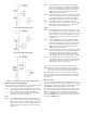
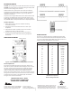
Relay Electrical Rangs
NO Contact 120V 208/240V
Full-load amps 9.8 Amps 4.9 Amps
Locked rotor amps 58.8 Amps 29.4 Amps
Resisve amps 9.8 Amps 4.9 Amps
Horsepower 1/2 HP 1/2 HP
NC Contact
Full-load amps 5.8 Amps 2.9 Amps
Locked rotor amps 34.8 Amps 17.4 Amps
Resisve amps 5.8 Amps 2.9 Amps
Horsepower 1/4 HP 1/4 HP
Pilot Duty: 125 VA at 120/208/240 VAC
Control Ambient Temperature
Operang -20°F to 140°F (-29°C to 60°C)
Storage -40°F to 176°F (-40°C to 80°C)
Ambient Humidity 0 to 95%, RH, Non-condensing
0 to 10V Output Impedance 1 K
Enclosure NEMA 1, Plasc
Agency Approvals UL Listed, File E94419, Guide XAPX
CSA Cered, File LR68340, Class 4813 02
ETC ORDERING INFORMATION
Uni-Line OEM Input No. of 0 - 10 V
Numbers Numbers Voltage Stages Output
ETC-211000-000 ETC-211020-000 120/240 2 No
ETC-211100-000 ETC-211120-000 120/240 2 Yes
ETC-212000-000 ETC-212020-000 24 2 No
ETC-212100-000 ETC-212120-000 24 2 Yes
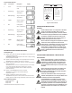
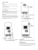
OPERATION
Liquid Crystal Display (LCD)
The LCD display provides a constant readout of the sensor temperature
and indicates if either of the two output relays is energized. When the
S1 annunciator is constantly illuminated during operaon, the Stage 1
relay is energized. Likewise, when the S2 annunciator is constantly
illuminated during operaon, the Stage 2 relay is energized. The display
is also used with the keypad to allow the user to adjust the setpoint
temperatures, dierenals and heang/cooling modes for each stage.
Backlight
When any mode key is pressed, the backlight is acvated and the ETC is
in control mode. Press the SET key to begin program mode.
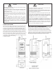
Control Setup
The temperature setpoint refers to the temperature at which the
normally open (NO) contacts of the output relay will open. Determine
the loads to be controlled and the operang modes required for each
stage, cooling or heang.
•
When the cooling mode is chosen, the dierenal is above the setpoint.
The relay will de-energize as the temperature falls to the setpoint.
• An-short Cycle Compressor Delay for cooling. Aer a relay
de-energizes, the ETC will prevent the relay from turning on unl a
congurable me has occurred to protect compressor.
•
When the heang mode is chosen, the dierenal is below the setpoint.
The relay will de-energize as the temperature rises to the setpoint.
The ETC two stage control can be set up for two stages of heang, two
stages of cooling or one stage cooling plus one stage heang. Refer to
Figures 1, 2 and 3 for a visual representaons of dierent control setups.