
Install Instructions

3
INSTALLATION INSTRUCTIONS
WARNING
Electrical Shock Hazard - Turn o power at the main
power source before installing the ETC control.
DO NOT restore electrical power to the unit unl the
ETC control is properly installed and cover assembled.
Fire Hazard - DO NOT locate the ETC control in an
explosive atmosphere as a re could result due to
possible spark generaon in the control.
All ETC Controls are designed as temperature controls
and are not used as temperature limit controls.
Where failure or malfuncon of the ETC control could
cause personal injury or property damage, other
devices (limit or safety controls) or systems (alarm
or supervisory) intended to warn or protect against
failure or malfuncon of the ETC control must
be installed.
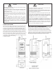
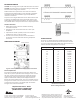
LOCKOUT :
LOCK
UNLOCK
USE COPPER CONDUCTORS ONLY
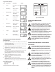
DISPLAY CODES
F FAHRENHEIT
C CELSIUS
H1 HEAT STAGE 1
C1 COOL STAGE 1
EP PROBE FAILURE/
OUT OF RANGE
EE EEPROM FAILURE
E1 IMPROPER KEY
E2 MEMORY ERROR
RELAY RATINGS N.O /N.C.
VAC
120
208/240
LRA
96/34.8 48/17.4
FLA
16/5.8 8/2.9
15/5.8 8/2.9
RES A
PILOT DUTY 125VA
1
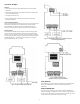
THERMOSTATS
52N8
Step Annunciator Descripon Display
1 F or C Fahrenheit or Celsius
Scale
2 S1 (blinking) Stage 1 Setpoint
Temperature
3 DIF 1 (blinking) Stage 1 Dierenal
Temperature
4 C1/H1 Stage 1 Cooling or
Heang Mode
5 D1 Cooling Delay
Set to 1-20 Minutes
6 S2 (blinking) Stage 2 Setpoint
Temperature
7 DIF 2 (blinking) Stage 2 Dierenal
Temperature
8 C2/H2 Stage 2 Cooling or
Heang Mode
9 D2 Cooling Delay
Set to 1-20 Minutes
Figure 4: Lockout Switch
INSTRUCTIONS CONCERNANT L’INSTALLATION
AVERTISSEMENT
Risque de choc électrique - Couper le courant à la
source d’alimentaon principale avant d’installer le
contrôleur ETC. NE PAS rétablir l’alimentaon élec-
trique de l’appareil avant que le contrôleur ETC ne
soit correctement installé et que le couvercle ne soit
assemblé.
Risque d’incendie - Ne pas placer le contrôleur ETC
dans une atmosphère explosive car un incendie
pourrait être déclenché par d’éventuelles éncelles
survenant dans le contrôleur.
Toutes les commandes de l’ETC sont conçues pour
contrôler la température et ne sont pas ulisées com-
me témoins des limites de température.
Si une défaillance du contrôleur ETC peut causer
des blessures ou des dommages matériels, d’autres
disposifs (contrôles des limites ou de la sécurité) ou
des systèmes (d’alarme ou de surveillance) desnés
à prévenir ou à protéger contre une défaillance ou un
dysfonconnement du contrôleur ETC, doivent être
installés.
TROUBLESHOOTING ERROR MESSAGES
Display Messages
E1 Appears when either the up Ç or down È key is pressed when not
in the programming mode.
To correct: If the E1 message appears even when no keys are being
pressed, replace the control.
E2 Appears if the control sengs are not properly stored in memory.
To correct: Check all sengs and correct if necessary.
EP Appears when the probe is open, shorted or sensing a temperature
that is out of range.
To correct: Check to see if the sensed temperature is out of range.
If not, check for probe damage by comparing it to a known
ambient temperature between -30°F and 220°F. Replace the
probe if necessary.
EE Appears if the EEPROM data has been corrupted.
To correct: This condion cannot be eld repaired.
Replace the control.
CL Appears if calibraon mode has been entered.
To correct: Remove power to the control for at least ve seconds.
Reapply power. If the CL message sll appears, replace the control.
Normal Operang Mode
Probe Temperature °F
Relay 1 ON S1
Relay 2 ON S2
*Note Cd alternates with temperature and relay
Program Mode Displays