
Install Instructions

5
CONTROL WIRING
General
• All wiring should conform to the Naonal Electric Code and local
regulaons.
• The total electrical load must not exceed the maximum rang of the
control (see Specicaons).
• Use copper conductors only.
• Electrical leads should not be taut; allow slack for temperature
change and vibraon.
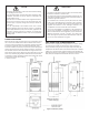
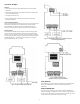
Input and Output Wiring
For typical wiring diagrams, refer to Figures 6 and 7. All connecons are
made to the power (lower) circuit board. When using the 24V AC
powered models, the 24V AC input lines must enter through the
sidewall of the case. Refer to Figure 5 for locaon of the entry hole.
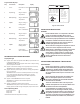
Analog Output
ETC models are available with an oponal 0 to 10 volt analog output.
This signal is a linear representaon of the sensor temperature with
0 volts = -30°F and 10 volts = 220°F. See gure 8 for wiring informaon
and Figure 5 for locaon of the entry hole. The reference for this output
is designated by the ”-” symbol on the wiring diagram. The output
signal is designated by the ”+” symbol.
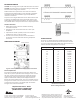
Figure 8: 0-10 V Analog Output
Located on Power (Lower) Circuit Board
Figure 7: Typical Wiring Diagram for 24 VAC Power Input
and Line Voltage Switching.
Figure 6: Typical Voltage Wiring Diagram.
FIELD REPAIRS
Field calibrang or repairs to the ETC control must not be aempted.
Sensors and replacement controls are available through Ranco
wholesalers.
SENSOR MOUNTING
For space sensing, mount the sensor where it will be unaected by
heat/cool discharge or radiated heat sources. Spot sensing requires the
sensor to be in good contact with the surface being sensed. The sensor
can be inserted in a bulb well for immersion sensing.