
Install Instructions

Customer Service Telephone 1.800.304.6563
Customer Service Facsimile 1.800.426.0804
HVACCustomerService@robertshaw.com
Robertshaw®, Ranco®, Paragon® and Uni-Line® are
trademarks of Robertshaw, its subsidiaries and/or
affiliated companies. All other brands mentioned
may be the trademarks of their respective owners.
For Technical Service
Telephone 1.800.445.8299
TechnicalService@robertshaw.com
www.robertshaw.com
©2018 Robertshaw
02/18 –352-00008-00 Rev C
6
EXTENDING SENSOR
CAUTION: Sensor wiring splices may be made external from the control.
CAUTION: Disconnect power to control before wiring to avoid possible
electrical shock or damage to the controller.
Addional cable can be spliced to the sensor cable to increase the
length beyond the standard 8 feet. It can be extended up to 400 feet.
The cable should be at least 22 AWG or larger to keep addional
resistance to a minimum.
All splices and wire lengths added to the sensor cable should be made
according to acceptable wiring pracces and should conform to the
Naonal Electrical Code and local regulaons. Use copper conductors
only. Shielded cable is not required. The sensor is not polarity sensive.
Checkout Procedure
1. Before applying power, make sure installaon and wiring
connecons are correct.
2. Apply power to the control and observe one or more cycles
of operaon.
3. If performance indicates a problem, check sensor resistance
to determine if sensor or control is at fault.
4. To check sensor resistance, disconnect sensor and measure
the resistance across the leads while measuring temperature
at the sensor.
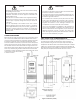
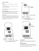
SENSOR REPLACEMENT
Figure 9: Sensor replacement on Display (Upper) Circuit Board.
Sensor Replacement
ETC models are available with Quick Connect Sensor feature that
allows for easy sensor replacement due to damage or wear. To access
the sensor connector, disconnect the power supply and open the
control. Remove single screw located in the center of the Display
Upper Circuit Board and carefully remove Display Board Circuit.
Remove Sensor Strain Relief to allow sensor to be removed from unit.
See Figure 5 for location of sensor strain relief. The sensor connection
is made at the P1 Connector on the Display Upper Circuit Board.
See figure 9 for connection information.
Replacement Sensor - Order
Uni-Line Number 1309007-044
(OEM Number 1309007-048)
Figure 10
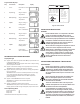
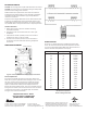
SPECIFICATIONS
The sensor is a negave temperature coecient (NTC) thermistor
sensor. The sensor resistance decreases with temperature increase.
It is .25 x 1.94 long with 8 feet #22 AWG cable. The thermistor has a
reference resistance of 30,000 ohms at 77°F (25°C).
Deg. C. Deg. F. RES. Nom.
-40 -40 1,010,000
-30 -22 531,000
-20 -4 291,200
-10 14 166,000
0 32 97,960
10 50 59,700
20 68 37,470
25 77 30,000
30 86 24,170
40 104 15,980
50 122 10,810
60 140 7,464
70 158 5,200
80 176 3,774
90 194 2,753
100 212 2,036
110 230 1,531
Figure 11:
Resistance vs Temperature
Sensor including 8 foot cable.
SENSOR CONNECTOR