INSTALLATION, OPERATING AND SERVICE INSTRUCTIONS RRG™ Series CAST IRON GAS-FIRED BOILER 9700609 BEFORE INSTALLATION: READ THIS MANUAL SAVE THESE INSTRUCTIONS Installing contractor and homeowner should read and be informed as to the proper installation and operation of this boiler. The manufacturer will not be responsible for improper installation or operation. This manual and all associated instruction material should be conspicuously posted near the boiler.
The City of New York requires a Licensed Master Plumber supervise the installation of this product. The Massachusetts Board of Plumbers and Gas Fitters has approved the RRG™ Series Boiler. See the Massachusetts Board of Plumbers and Gas Fitters website, http://license.reg.state.ma.us/pubLic/pl_products/pb_pre_form.asp for the latest Approval Code or ask your local Sales Representative. The Commonwealth of Massachusetts requires this product to be installed by a licensed Plumber or Gas fitter.
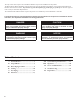
Table 1A: Connection Sizes (1) Boiler Model Supply NPT (inch) Return NPT (inch) Vent (1) (inch) Gas NPT (inch) Relief Valve NPT (inch) Drain NPT (inch) RRG062 RRG096 RRG130 RRG164 1¼ 1¼ 1¼ 1¼ 1¼ 1¼ 1¼ 1¼ 4 5 6 6 ½ ½ ½ ½ ¾ ¾ ¾ ¾ ¾ ¾ ¾ ¾ Refer to the National Fuel Gas Code for equivalent areas of circular and rectangular flue linings.
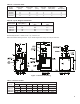
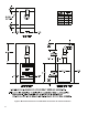
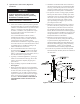
Figure 2: Minimum Clearances to Combustible Construction for Closet Installation 4
I. Pre-Installation WARNING Carefully read all instructions before installing boiler. Failure to follow all instructions in proper order can cause personal injury or death. A. Inspect shipment carefully for any signs of damage. All equipment is carefully manufactured, inspected and packed. Our responsibility ceases upon delivery of boiler to carrier in good condition. Any claim for damage or shortage in shipment must be filed immediately against carrier by consignee.
III. Water Piping and Trim WARNING Failure to properly pipe boiler may result in improper operation and damage to boiler or building. A. Design and install boiler and system piping to prevent oxygen contamination of boiler water. Oxygen contamination sources are system leaks requiring addition of makeup water, fittings, and oxygen permeable materials in distribution system.
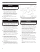
Figure 4: Recommended Water Piping for Zone Valve Zoned Heating Systems
Figure 5: Recommended Water Piping for Circulator Zoned Heating Systems
I. Optional LWCO and Auxiliary High Limit Installation WARNING DO NOT ATTEMPT to cut factory wires to install an aftermarket Low Water Cut Off (LWCO). Only use connections specifically identified for Low Water Cut Off. In all cases, follow the Low Water Cut Off (LWCO) manufacturer’s instructions. 6. Installation of manual shutoff valve located above the LWCO and the boiler is recommended to allow servicing. Thus LWCO probe can be removed for inspection without draining the heating system.
IV. Venting flue collector. See Figure 1. Secure with sheet metal screws. 5. Verify power cord, mounting bracket and Blocked Vent Switch are secure and located as shown in Figure 7. WARNING WARNING Do not alter boiler draft hood or place any obstruction or non-approved damper in the breeching or vent system. Flue gas spillage can occur. ETL certification will become void. Failure to properly install and use this Blocked Vent Switch may result in property damage, personal injury or loss of life. A.
1. The vent damper must be the same size as the outlet of the Draft Hood supplied with the boiler (see Table 1A). Unpack the damper carefully - DO NOT FORCE IT CLOSED! Forcing the damper may damage the gear train and void the warranty. 2. Mount the vent damper assembly onto the canopy/ diverter. (Refer to Figure 7 and to instructions packed with the vent damper for specific instructions). Do not modify either the draft hood or vent damper. NOTICE Provide adequate clearance for servicing. 3.
V. Gas Piping A. Size gas piping. Design system to provide adequate gas supply to boiler. Consider these factors: 1. Allowable pressure drop from point of delivery to boiler. Maximum allowable system pressure is ½ psig. Actual point of delivery pressure may be less; contact gas supplier for additional information. Minimum gas valve inlet pressure is listed on rating label. 2. Maximum gas demand. Consider existing and expected future gas utilization equipment (i.e. water heater, cooking equipment). 3.
VI. Electrical A. General. Install wiring and electrically bond boiler to ground in accordance with requirements of authority having jurisdiction, or in absence of such requirements, with the National Electrical Code, ANSI/NFPA 70. B. Install thermostat. Locate on inside wall approximately 4 feet above floor. Do not install on outside wall, near fireplace, or where influenced by drafts or restricted air flow, hot or cold water pipes, lighting fixtures, television, or sunlight.
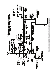
Figure 9: Wiring Connection Diagram
Figure 10: Schematic Ladder Diagram 15
Figure 11: Wiring Schematic, Zone Valves Figure 12: Wiring Schematic, Zone Circulators 16
VII. System Start-up and Checkout A. Main Burner Check - Check main burners to see that they were not dislodged during shipment. Rear of burners should be in the vertical slots in the rear of burner tray and the front of the burners should be seated completely on the orifices. B. Initial start 1. Fill entire heating system with water and vent air from system. Use the following procedure on a System equipped with zone valves. a. Close isolation valve in boiler supply piping. b.
Figure 14: Operating Instructions 18
6. Natural Gas Input: Adjust Regulator on Gas Valve so that manifold pressure is 3½ inches water column. Turning Regulator Adjusting Screw Clockwise increases pressure. Counter-clockwise rotation decreases pressure. D. Check Main Burner Flame. See Figure 15. Flame should have a clearly defined inner cone with no yellow tipping. Orange-yellow streaks caused by dust should not be confused with true yellow tipping. Figure 16: Pilot Burner Flame G. Check Vent Damper Operation.
VIII. Operation B. BOILER FAULT A. BOILER SEQUENCE OF OPERATION In the event the boiler fails to start, the control provides status information to help determine the cause of the problem. Table 4 from Section X: Troubleshooting (page 24) provides a list of boiler flash codes indicating the source of the lockout. Refer to the Troubleshooting Section for more information. NORMAL OPERATION 1. The RRG Series Boilers are equipped with an Integrated Boiler Control (IBC).
2. Outdoor Reset Differential Setpoint (when outdoor sensor installed) The Outdoor Reset Differential Setpoint is user adjustable by turning the bottom knob labeled “OUTDOOR RESET DIFF”. Adjustment range is 0°F to 50°F. When no outdoor sensor is present, the IBC uses the user setpoint as the operating setpoint. When an outdoor temperature sensor is attached, the IBC adjusts the Conditioned space demand operating setpoint based on outdoor temperature. See graph below.
IX. Service and Maintenance Important Product Safety Information Refractory Ceramic Fiber Product Warning: The Repair Parts list designates parts that contain refractory ceramic fibers (RCF). RCF has been classified as a possible human carcinogen. When exposed to temperatures above 1805°F, such as during direct flame contact, RCF changes into crystalline silica, a known carcinogen.
WARNING Service on this boiler should be undertaken only by trained and skilled personnel from a qualified service agency. Inspections should be performed at intervals specified in this manual. Maintain manual in a legible condition. Keep boiler area clear and free of combustible materials, gasoline and other flammable vapors and liquids. Do not place any obstructions in boiler room that will hinder flow of combustion and ventilation air. A. General. Inspection and service should be conducted annually.
X. Troubleshooting A. Before troubleshooting The following pages contain troubleshooting tables for use in diagnosing control problems. When using these tables the following should be kept in mind: 1. This information is only meant to be used by a professional heating technician as an aid in diagnosing boiler problems. 2. In general, these tables assume that there are no loose or miswired electrical connections.
B. Use Control LEDS To Direct TroubleShooting Efforts If the control detects an error, the LEDs will flash. Use the LEDs to identify the boiler problem and corrective action in the table below. If LEDs are not flashing, proceed to Paragraph C: Flashing LEDs Status Recommended Corrective Action Boiler or Control is not powered No 120 Vac Power at boiler, check breaker and wiring between breaker panel and boiler POWER Steady 1 Hz flash Line Voltage Reversed Reverse polarity of 115 VAC supply voltage.
C. Use status LEDS To guide TroubleShooting The control LEDs will light to indicate status. Use these LEDs to identify the boiler problem in the table below: 1. Boiler and Circulator Off LED / Status Recommended Corrective Action The boiler has not detected a call for heat - POWER Standby Burner off Circulator off Check that the thermostat: - When a thermostat call for heat is detected control TSTAT/CIRC LED will be lit.
4. Circulator is On But Damper is Not Open LED / Status Recommended Corrective Action The control is waiting for the damper to open. Damper end switch has failed to close (end switch contact is stuck open). Combustion can never take place unless the damper blade is in the fully open position. Check the following: - POWER - TSTAT/CIRC - LIMIT Damper Failed to Open - Confirm if control terminal “P6 - 5” (yellow wire) is energized.
5. Circulator is On, Damper is Open But Boiler Fails to Start (continued) LED / Status Recommended Corrective Action 1. No Spark a. Can you hear sparking? - If there is no spark noise replace the control. b.
XI. Repair Parts All RRG™ repair parts may be obtained by contacting your local Rand & Reardon Distributor. Section Assembly and Canopy Assembly.....................................30 Base Assembly.............................................................................32 Burner Tray, Main Burners and Manifold....................................34 Pilot Burner and Gas Valve..........................................................36 Jacket Assembly, Complete.............................................
Key No.
Section Assembly and Canopy Group 31
Key No.
Key No.
Manifold and Main Burners 35
Key No. Description Part Number Boiler Model RRG062 RRG096 RRG130 RRG164 Pilot Burner and Gas Valve (Natural or LP/Propane Gas) 33 34 35 36 36 Pilot Burner, Honeywell Q3481B1206 (Nat. Gas) 103704-01 1 1 1 1 Pilot Burner, Honeywell Q3481B1420 (LP) 103705-01 1 1 1 1 Ground Wire Assembly 103776-01 1 1 1 1 Pilot Tubing 1/4" OD x 30" Lg. Aluminum 8236122 1 1 1 --- Pilot Tubing 1/4" OD x 40" Lg. Aluminum 8236123 --- --- --- 1 Gas Valve, Honeywell VR8204C3007 (Nat.
Key No.
Key No.