
Installation Guide


12
A. Size gas piping. Design system to provide adequate gas
supply to boiler. Consider these factors:
1. Allowable pressure drop from point of delivery to
boiler. Maximum allowable system pressure is ½
psig. Actual point of delivery pressure may be less;
contact gas supplier for additional information.
Minimum gas valve inlet pressure is listed on rating
label.
2. Maximum gas demand. Consider existing and
expected future gas utilization equipment (i.e. water
heater, cooking equipment).
3. See Table 1B for boiler inputs.
B. Connect boiler gas valve to gas supply system.
1. Use methods and materials in accordance with local
plumbing codes and requirements of gas supplier. In
absence of such requirements, follow National Fuel
Gas Code, ANSI Z223.1/NFPA 54.
2. Use thread (joint) compounds (pipe dope) resistant
to action of liqueed petroleum gas.
V. Gas Piping
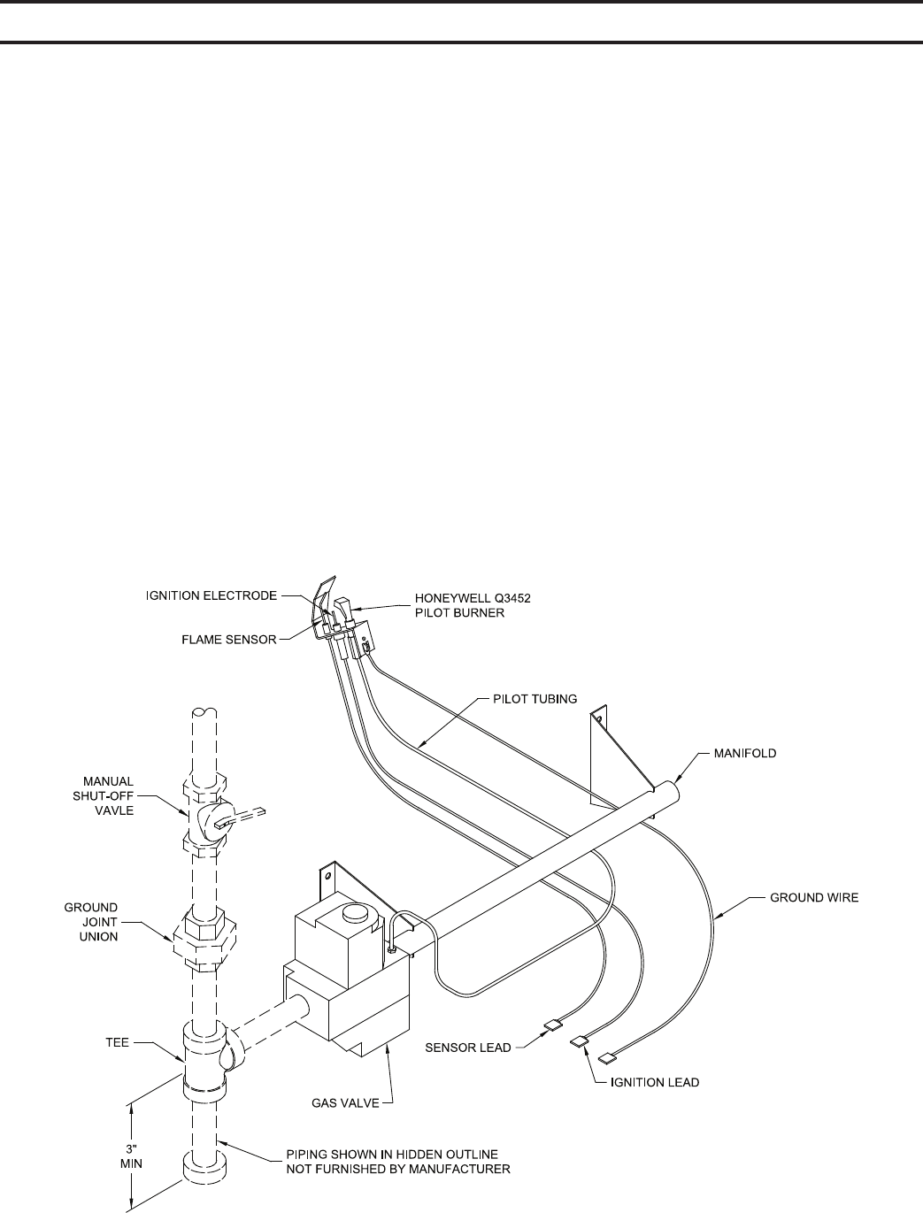
Figure 8: Pilot and Gas Piping
3. Install sediment trap, ground-joint union and manual
shut-off valve upstream of boiler gas control valve.
See Figure 8.
4. All above ground gas piping upstream from manual
shut-off valve must be electrically continuous and
bonded to a grounding electrode. Do not use gas
piping as grounding electrode. Refer to National
Electrical Code, ANSI/NFPA 70.
C. Pressure test. The boiler and its gas connection must
be leak tested before placing boiler in operation.
1. Protect boiler gas control valve. For all testing over
½ psig, boiler and its individual shutoff valve must
be disconnected from gas supply piping. For testing
at ½ psig or less, isolate boiler from gas supply
piping by closing boiler's individual manual shutoff
valve.
2. Locate leaks using approved combustible gas
detector, soap and water, or similar nonammable
solution. Do not use matches, candles, open ames,
or other ignition source.