
Manual


Manual-1
AC 22B
ACTIVE CROSSOVER
OPERATORS MANUAL
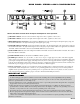
AC 22B CONNECTION
In agreement with IEC and AES/ANSI standards, AC 22B
wiring convention is pin 2 Positive, pin 3 Negative (return),
pin 1 Signal ground (for unbalanced use), with the connector
case or shell tied to chassis ground.
BALANCED OPERATION
Use only when driving from a true balanced source and
driving to a true balanced destination—either transformer
coupled or active drive. Connect the input to pins 2 and 3
with pin 2 positive. Do not connect pin 1. Terminate the
shield to the case or shell. Connect the output to pins 2 and 3
with pin 2 positive. Do not connect pin 1. Connect the shield
to the case or shell.
UNBALANCED OPERATION
Connect the input between pins 2 and 1 with pin 2 positive
and pin 1 Signal ground. Short pin 3 to pin 1. Terminate the
shield to the case or shell. Connect the output between pins 2
and 1 with pin 2 Positive. Leave pin 3 open—do not short it
to pin 1. Connect the shield to the case or shell.
COMBINATION OPERATION
For combined balanced and unbalanced operation, use
whichever half of the above instructions apply for each end.
See the “Sound System Interconnection” RaneNote
included with this manual for more information on cabling
and grounding requirements.
QUICK START
The AC 22B can be either a Stereo 2-Way or Mono 3-Way crossover. Labels above the controls refer to the unit being
operated in the 2-Way Stereo mode. Labels below the controls refer to the unit being operated in the 3-Way Mono mode.
The AC 22B is a fully balanced output version of the popular AC 22 and is equipped with XLR conectors instead of
the standard ¼" TRS jacks. All other features, specifications and operation are identical with the standard model with an
added switch. Where the AC 22 is configured somewhat automatically by using switching jacks, the AC 22B is config-
ured by a SYSTEM MODE switch added to the back of the unit.
To operate the AC 22B in Stereo 2-Way mode, be sure that the Mode switch is set for STEREO 2-WAY. Follow the
labels above the controls and jacks.
When operated in the Mono 3-Way mode, the switch should be set in the MONO 3-WAY position. Follow the labels
below the controls and jacks. In Mono 3-Way mode the Channel 1 High Output is unusable. This output is the high-pass-
only portion of the midrange filter. The Channel 1 High Level and the Channel 2 Master Level are also defeated on the
front panel.
NEVER CONNECT ANYTHING EXCEPT AN RS 1 OR OTHER APPROVED RANE AC POWER SUPPLY
TO THE THING THAT LOOKS LIKE A TELEPHONE JACK ON THE REAR. This is an AC supply and requires
some special attention if you do not have an operational power supply EXACTLY like the one that was originally
packed with your unit.
WEAR PARTS: This product contains no wear parts.