
Manual


Manual-2
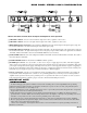
FRONT PANEL: STEREO 2-WAY CONFIGURATION
Observe the labels screened above the controls for stereo operation.
POWER switch: Self-evident.
POWER indicator: When this yellow LED is lit the unit is ready to operate.
CHANNEL 1 MASTER LEVEL controls the overall Level of Channel 1 without altering the relative settings of the HIGH
and LOW Outputs. Unity gain for all LEVEL controls is at “7”.
LOW LEVEL controls the Level of signal going to the LOW Output in this Channel. In the MONO SUB mode the Channel
1 LEVEL control sets the Level of the MONO SUB Output, Channel 2's LEVEL control is inactive.
LOW MUTE: When pressed to the in position, all signal is removed from the LOW Output. This eases tune-up procedures,
as described on pages Manual-7 through 13. In the MONO SUB mode, the Channel 1 LOW MUTE switch mutes the
MONO SUB Output, Channel 2's MUTE is inactive.
LOW TIME DELAY control adds from 0 to 2 ms of time Delay to the LOW OUT only. This allows a low frequency driver
to be electronically phase-aligned with a high frequency driver whose diaphragm is situated behind the low frequency
diaphragm. Refer to Time Delay Adjustment on page Manual-6. NOTE: Both DELAY controls are inactive in the MONO
SUB mode.
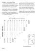
LOW/HIGH FREQUENCY: This 41-detent selector determines the crossover Frequency between the LOW and HIGH
Outputs. The detents assure maximum accuracy and consistency between Channels. Refer to Selecting Crossover Frequen-
cies on page Manual-6 to determine the proper setting for your particular system.
HIGH LEVEL controls the Level of signal going to the HIGH Output in this Channel.
CHANNEL 2 MASTER LEVEL controls the overall Level of Channel 2 without altering relative settings of the HIGH and
LOW Outputs.