
Specifications


Manual-10
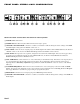
Delay vs. Frequency Table
If you do not have the equipment necessary to electroni-
cally align the system as described in the previous sections,
you may use the table below to obtain a rough and approxi-
mate phase alignment of your drivers. Measure the horizontal
displacement between the voice coils of the two adjacent
drivers sharing the same crossover point, then find the
column in the table nearest your actual displacement. Move
down this column to the proper Crossover Frequency as
indicated on the left of the table: the corresponding DELAY
knob setting will then be the closest for your system. For
example, if you have a two-way system crossed over at 800
Hz with the compression driver voice coil located about 9"
behind the woofer voice coil, the Delay knob setting corre-
sponding to a 9" displacement at 800 Hz on the table would
be “5” as indicated on the front panel.
In order to phase-align two drivers you must observe only
the crossover frequency, which is common to both drivers.
Pink noise can be used if all other frequencies are disre-
garded, since room acoustics and imperfect driver response
will cause erroneous alignment attempts. Using pink noise as
a source, each driver is individually tuned to an arbitrary 0
dB level on the analyzer display only at the crossover
frequency. When both are turned on simultaneously, the
combined response of the two drivers should read +3 dB
higher at the crossover frequency on the display. If the drivers
are not phase-aligned, some cancellation will occur on-axis,
resulting in a combined response less than +3 dB. Turning up
the DELAY control causes the lower driver to electronically
move backward until the analyzer reads +3 dB; then the two
drivers are electronically aligned and the on-axis cancellation
is eliminated (see Figure 2 on page Manual-6).
Voice Coil Displacement (Inches)
(Hz) .75" 1.5" 3" 6" 9" 12" 15" 18" 21" 24"
70 11.522.53.55678MAX
80 11.522.53.55678MAX
100 11.522.53.55678MAX
150 11.522.53.5567MAX
200 11.522.53.5567MAX
250 11.522.53.5578MAX
300 1 1.5 2 2.5 3.5 5.5 7 MAX
400 11.522.5468MAX
450 11.522.5468MAX
500 11.522.5468MAX
800 11.52357MAX
lk 1 1.5 2.2 3 6 MAX
1.2k 1 1.5 2.2 3.5 MAX
1.5k 1 1.5 2.3 3.5 MAX
2k 1 1.5 2.3 MAX
2.5k 1 1.5 2.3 MAX
3k 1 1.7 2.4 MAX
3.6k 1 1.7 MAX
4k 1 1.8 MAX
6k 12MAX
7k 1.2 MAX
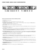
Crossover Frequency
Displacement
Fig. 3. Vertical Driver Displacement