
Owner's manual


Manual-17
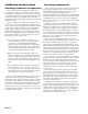
occasionally there is a need to delay the CD horn as its
diaphragm is usually in front of the other drivers in the
enclosure (see Fig. 5). If you are using CD horns, you should
also read the CD horn EQ modification as described on page
18.With the AC 23 it is a little difficult to figure out which
Delay to move to the High Frequency Output. The normal
configuration for a speaker enclosure is shown in Fig. 3. The
long throw horn’s driver is the farthest back in the enclosure,
so no Delay is needed for this driver. Some Delay is needed
on the Low and Mid drivers. The enclosure with the CD
Horn, shown in Fig. 5, needs the Delay circuit transplanted
from the Low to the High frequencies Outputs. As can be
seen from the dashed line in the drawing, the CD Horn’s
driver is in front of the mid and low drivers. Of the three
drivers, the low frequency driver will need no Delay, the mid
frequency driver will need some Delay, and the CD Horn will
need the most Delay. Soldering is required. This modification
should only be attempted by an experienced technician.
STEP BY STEP PROCEDURE
Transplanting the Low Frequency Delay to the High
Frequency Output.
CHANNEL ONE:
1. Refer to the board layout on the back page.
2. Behind the Channel 1 LF DELAY pot find the jumper
labeled W6. Behind the Channel 1 LF LEVEL pot find the
jumper labeled W3.
3. To remove the Delay 1 circuit from the Low Frequency
output, remove both the W6 and W3 jumpers.
4. To get the Low Frequency output to work again, install a
long jumper from W6 Pin 1 to W3 Pin 2.
5. The Delay 1 circuit is now removed from all circuits.
6. To install the Delay 1 circuit into the Channel 1 High
Frequency Output, find the jumper W10 behind the
Channel 1 MF MUTE switch and remove it.
7. Install a long jumper from W6 Pin 2 to W10 Pin 1, and
install a long jumper from W3 Pin 1 to W10 Pin 2.
The Delay 1 circuit is now installed into Channel 1 High
Frequency Output.
CHANNEL TWO:
1. Refer to the board layout on the back page.
2. Behind the Channel 2 LF DELAY pot find the jumper
labeled W28. Behind the Channel 1 LF LEVEL pot find
the jumper labeled W22.
3. To remove the Delay 3 circuit from the Low Frequency
output, remove both the W28 and W22 jumpers.
4. To get the Low Frequency output to work again, install a
long jumper from W28 Pin 1 to W22 Pin 1.
5. The Delay 3 circuit is now removed from all circuits.
6. To install the Delay 3 circuit into the Channel 2, High
Frequency Output, find the jumper W33 behind the
Channel 2 MF MUTE and remove it.
7. Install a long jumper from W28 Pin 2 to W33 Pin 1, and
install a long jumper from W22 Pin 2 to W33 Pin 2.
The Delay 3 circuit is now installed into Channel 2 High
Frequency Output.
STEP BY STEP PROCEDURE
Transplanting the Mid Frequency Delay to the High
Frequency Output
CHANNEL ONE:
1. Refer to the board layout on the back page.
2. Behind the Channel 1 MF DELAY pot find the jumper
labeled W12. Behind the Channel 1 MF LEVEL pot find
the jumper labeled W9.
3. To remove the Delay 2 circuit from the Mid Output,
remove both the W12 and W9 jumpers.
4. To get the Mid Frequency output to work again, install a
long jumper from W12 Pin 1 to W9 Pin 2.
5. The Delay 2 circuit is now removed from all circuits.
6. To install the Delay 2 circuit into the Channel 1, High
Frequency output, find the jumper W10 behind the
Channel 1 MF MUTE switch and remove it.
7. Install a long jumper from W12 Pin 2 to W10 Pin 1, and
install a long jumper from W9 Pin 1 to W10 Pin 2.
The Delay 2 circuit is now installed into Channel 1 High
Frequency Output.
CHANNEL TWO:
1. Refer to the board layout on the back page.
2. Behind the Channel 2 MF DELAY pot find the jumper
labeled W36. Behind the Channel 2 MF LEVEL locate the
jumper labeled W32.
3. To remove the Delay 4 circuit from the Mid Frequency
output, remove both the W36 and W32 jumpers.
4. To get the Mid Frequency output to work again, install a
long jumper from W36, Pin 1 to W32, Pin 2.
5. The Delay 4 circuit is now removed from all circuits.
6. To install the Delay 4 circuit into the Channel 2, High
Frequency output, find the jumper W33 behind the
Channel 2 MF MUTE switch and remove it.
7. Install a long jumper from W36, Pin 2 to W33, Pin 1, and
install a long jumper from W32, Pin 1 to W33, Pin 2.
The Delay 4 circuit is now installed into Channel 2 High
Frequency Output.