
Owner's manual


Manual-9
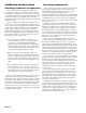
REAR PANEL: ALTERNATE MONO 4-WAY INSTALLATION
Note: The internal switching in the AC 23 will result in a Mono 4-Way configuration with the crossover
sections arranged SUB, LOW, MID & HIGH from left to right across the front panel. By connecting a patch
cable from the CHANNEL 1 HIGH OUT to the CHANNEL 2 INPUT, the LOW/MID crossover range changes
from 70 Hz - 1 kHz to a higher range of 190 Hz - 7 kHz.Set the CHANNEL 1 switch to 3-WAY, and the
CHANNEL 2 switch to 2-WAY.
WARNING: NEVER OPERATE IN ALTERNATE MONO 4-WAY MODE WITH CHANNEL 1 INPUT UNCON-
NECTED. OTHERWISE A POSSIBLY DESTRUCTIVE OSCILLATION MAY OCCUR.
CAUTION: NEVER PLUG OR UNPLUG THE PATCH CORD WITH THE AC 23 OR AMPLIFIER POWER ON,
OTHERWISE POSSIBLE DAMAGE MAY OCCUR TO YOUR SPEAKERS.
햲 MONO INPUT: These ¼" Inputs accept either balanced TRS (tip-ring-sleeve) or unbalanced TS (tip-sleeve) plugs.
Connect the output from your mixer or other signal source only to the CHANNEL 1 INPUT for Mono operation; do not use
the Channel 2 input. Note: For this alternate Mono 4-Way installation, connect a patch cord from the CHANNEL 1 HIGH
OUT to the CHANNEL 2 INPUT as shown. See warnings above.
햳 SUBWOOFER OUTPUT: These are ¼" TS (tip-sleeve) unbalanced Output jacks. Connect the SUB OUT to the input of
the subwoofer amplifier (or bass bin amp).
햴 LOW FREQUENCY OUTPUT: Connect the MID OUT to the input of the low frequency (or mid-bass) amp.
햵 MID FREQUENCY OUTPUT: Connect the HI MID OUT to the input of the mid frequency amplifier.
햶 Hl FREQUENCY OUTPUT: Connect the HIGH OUT to the input of the high frequency amplifier.
햷 2-WAY/3-WAY SWITCHES: Converts each channel from 3-Way to 2-Way. For this configuration, slide the CHANNEL 1
switch to 3-WAY, and the CHANNEL 2 switch to 2-WAY.
햸 Power input connector: Use only a model RS 1 or other power supply approved by Rane. This unit is supplied with an 18
VAC center tapped remote power supply suitable for connection to this input jack. Consult Rane for a replacement or
substitution.
햹 Chassis ground point: A #6-32 screw is used for chassis grounding purposes. Always connect the crossover chassis to the
amplifier chassis. See the CHASSIS GROUNDING note on page Manual-7 for details.