
Manual


Manual-3
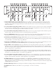
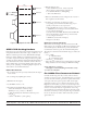
1 3-WAY / 4-WAY switch: Converts the outputs from 3-Way to 4-Way. is switch removes the Hi-Mid frequency crossover from
the signal path — the HI-MID / HIGH Frequency control and all HI-MID controls are disabled. e MID / HI-MID Frequency
control becomes the MID / HIGH Frequency control.
2 CHANNEL A and B INPUTS: Plug the outputs of the mixer, equalizer or other source to these Inputs.*
3 LOW Outputs: Connect the CHANNEL A LOW Output to the left channel input of the low frequency amplifier, and the
CHANNEL B LOW Output to the right channel input of the low amplifier. If you need a summed Mono Low Output, use the
CHANNEL A Output (see 7).*
4 MID Outputs: Connect the CHANNEL A MID Output to the left channel input of the amplifier, and the CHANNEL B Mid
Output to the right channel input of the amplifier.*
5 HI-MID Outputs: Are only used in 4-WAY mode. Connect the CHANNEL A HI-MID Output to the left channel input of the
amplifier, and the CHANNEL B HI-MID Output to the right channel input of the amplifier.*
6 HIGH Outputs: Connect the CHANNEL A HIGH Output to the left channel input of the high frequency amp, and the CHAN-
NEL B HIGH Output to the right channel input of the high frequency amp.*
7 CHANNEL A LOW Output: Connect this Output to the input of the low frequency amplifier when the MONO LOW switch is
activated on the front panel. It contains the sum of both CHANNEL A and B LOW signals.*
8 SUM Outputs: Are a sum of the LOW, MID, HI-MID, and HIGH Outputs. e Sum Outputs are useful to connect to instru-
mentation devices as indicated in the setup procedure. Use the Sum Outputs for split-band EQ and/or split-band Limiter applica-
tions. When using the Sum Outputs, it is important to note that CD Horn EQ and Delays affect the summed output. If you want a
flat response, do not use delay or CD Horn EQ when using these Sum Outputs.*
9 Output INVERT switches: may assist in keeping drivers in-phase without having to rewire connections. Linkwitz-Riley filter Out-
puts are always in phase with correct polarity. Be sure the amplifiers are off before changing any of these switches.
0 Power connector: Uses the standard cord provided. Inside the AC 24 is a universal internal switching power supply that accepts
100 to 240 VAC at 50 to 60 Hz, allowing it to work in most countries.
*Note: In agreement with IEC and AES/ANSI standards, wiring convention is pin 2 positive, pin 3 is negative (return), pin 1 is shield chassis
ground.
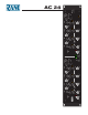
AC 24
SUM HIGH HI-MID MID LOW INPUT
3-WAY 4-WAY
MADE IN U.S.A.
RANE CORP.
INVERTINVERTINVERT
(HI-MID UNUSED)
INVERT INVERT INVERT INVERT INVERT
100-240V
20 WATTS50/60 Hz
FOR CONTINUED
GROUNDING
PROTECTION
DO NOT REMOVE
SCREW
CHANNEL
B
CHANNEL
A
SUM HIGH HI-MID MID LOW
MONO LOW
INPUT
4-WAY 4-WAY
This device complies with Part 15 of the FCC Rules. Operation is
subject to the following two conditions: (1) this device may not cause
harmful interference, and (2) this device must accept any interference
received, including interference that may cause undesired operation.
WIRING
PIN 2 = POSITIVE
PIN 3 = NEGATIVE
PIN 1 = CHASSIS GROUND
COMMERCIAL AUDIO
EQUIPMENT 24TJ
R
ACN 001 345 482
8 6 5 4 3 2 8 6 5 4 7 2
1 910 9