
Manual


Manual-5
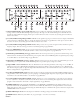
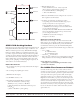
Fig. 2 In-Phase Axis Response Without Signal Delay
Fig. 3 Corrected In-Phase Axis Response with Delay on Low Driver
Signal Delay Adjustment Method One
If you can not get your hands on the equipment necessary to
electronically align the system, it is possible to set the delays using
only the horizontal displacement of the sound sources. It is very
important to make certain that all drivers have correct polarity before
setting signal alignment delay. First, let’s review the basic informa-
tion required for the task.
• e general equation for the speed of sound in dry air is:
331.4+0.6Tc m/s
Tc = temperature in degrees Celsius,
m = meters and
s = seconds
• For those still having diculty accepting the metric system, the
following approximation will do:
13.57 inches / millisecond at 72° Fahrenheit.
34.5 cm / millisecond at 22° Celsius.
• e AC 24 provides 10 ms of delay. Each dot on the silkscreen
represents 1 ms or 13.57 inches (at 72 °F).
• is allows delay compensation for distances ranging from 0.0
to 135 inches (11.3 feet) [343 cm].
• e resolution of the adjustment is about 0.6 inch [1.5 cm].
Important Note: e horizontal location of a driver is deter-
mined by the front of the voice coil.
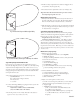
Method One, Step-by-Step
1. Identify the driver that is the furthest away from the front of
the stack. is driver gets zero delay. e horizontal displace-
ment of all other drivers is measured relative to this driver.
2. Take the distance, measured in inches, for each driver and divide
by 13.57. is gives the delay in milliseconds and pot rotation
in “fractional-dots.” See Figure 4.
Signal Delay Adjustment Method Two
OK, so you want to do this the hard way. e following example
outlines one method for Signal Delay alignment of the system in
Figure 4. e procedure easily adapts to other configurations.
Required tools: Realtime Analyzer
Cautions/considerations: With 4
th
-order filters, it’s impor-
tant to accurately identify crossover frequency settings before
adjusting delay. A reference level must be set for each driver at
each crossover point. is eliminates errors due to non-flat driver
response and room acoustics. When using a ⅓-octave realtime ana-
lyzer, best results are achieved if crossover points are set to the nearest
⅓-octave center.
Method Two, Step-by-Step
1. Initial AC 24 control settings:
a. Leave FREQUENCY controls as set in Step One.
b. MUTE all Outputs.
c. Set Input and Output LEVEL controls to unity (the mark
between the 8
th
and 9
th
dots).
d. Set DELAYS to zero.
e. Switch CD HORN EQs off.
f. Set LIMITERS to 0 dB FS.
g. Set all rear INVERT switches to the out (non-inverting)
position (assuming all drivers are in phase).
2. Connect the RTA to the AC 24:
a. Connect Pink Noise output to Crossover Input.
b. Connect AC 24 Sum Output to RTA Line Input.
c. Set RTA Scale to 3 dB if available.
d. Turn on Pink Noise.
3. Adjust crossover frequencies to ISO centers:
a. For this crossover frequency calibration you are looking at
the line level Sum output and NOT the acoustic output.
b. Amplifiers off.
c. UnMUTE the AC 24 Low Output.
i) e 1
st
6 dB red LED on the RTA indicates the
Low / Mid crossover frequency.
ii) Adjust the LOW / MID Frequency to just light the
1
st
–6 dB red LED closest to the desired crossover
frequency.