
User Manual


Manual-2
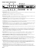
FRONT PANEL DESCRIPTION
SIGNAL LEDs: illuminate green 34 dB before clipping.
SENSITIVITY controls: vary incoming signal levels to the A to D converter. The output signal is also adjusted so the AD
22B always passes signal with unity gain. (See operating instructions.)
CLIP LEDs: illuminate red 4 dB before clipping at the A to D converter input.
BYPASS buttons & LEDs: These momentary push buttons toggle each Channel’s hard-wired Bypass. If an LED is on, the
given Channel is Bypassed and functions like a wire. If it is off the given channel is active.
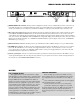
STORE LED: flashes green when the current configuration of the AD 22B is different from the stored configuration. The
STORE LED is off when the current configuration matches the stored configuration.
STORE button: Stores the current Delay configuration into both Channel’s current Memory (A or B). The current Memory
for each Channel is indicated by the MEMORY LED which is lit when editing that Channel.
MEMORY LEDs: indicate the most recently recalled Memory, A or B, for each Channel by illuminating yellow. They also
indicate the Memory that is written to when the STORE button is pressed. The MEMORY LED flashes when the current
Delay value for the selected Channel is different than the stored value for the selected Channel.
RECALL button: Pressing this pushbutton alternately Recalls stored Memories A and B, for the Channels(s) indicated by
the green CHAN LEDs.
CHANNEL LEDs: indicate the Channel number whose value is currently being displayed in the LED display and whose
current Delay value is editable by illuminating green. If both CHAN LEDs are on, both Channel’s current Delay values are
editable. In this edit BOTH mode, the LED display shows the smaller of the two current Delay values and the memory
LEDs turn off if the two Channel’s current Memories are not the same.
CHANNEL button: Pressing this button advances the Channel LEDs from CHAN 1 to CHAN 2 to BOTH. The current
Delay value of the selected Channel is displayed in the LED display. (This button does nothing in Mono Mode.)
DISPLAY MODE button & LEDs: This button changes the units of displayed Delay values from Milliseconds to Feet to
Meters. The LEDs indicate the current Display Mode: MILLISECONDS, FEET or METERS.
5 digit LED display: indicates the current Delay value for the selected Channel. When both Channels are selected, the
smaller of the two Channel’s current Delay values is displayed. This display also shows the current temperature setting when
holding down the DISPLAY MODE button and pressing one of the up/down buttons. On power-up the current software
revision level and internal Stereo/Mono (2CHAN/1CHAN) configuration are displayed.
UP/DOWN buttons: Pressing these buttons increases/decreases the amount of Delay in the selected Channel(s). The two
buttons just to the right of the LED display change Delay time in 1 millisecond steps. The far right buttons provide 10
microsecond steps. For distance displays (feet and meters), these buttons are FINE and COARSE adjustments, since Delay
increments are always in 1 msec and 10 µsec steps, regardless of the DISPLAY MODE.
TEMPERATURE setting: Holding down DISPLAY MODE while pressing the up/down buttons displays the current
temperature setting in degrees Celsius for the 1 msec/COARSE buttons and degrees Fahrenheit for the 10 µsec/FINE
buttons. Further up/down presses change the temperature setting. No matter which unit (°C or °F), adjustments are always in
1°C steps (or 1.8°F).