
User Manual


Manual-3
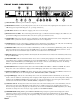
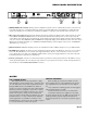
REAR PANEL DESCRIPTION
REMOTE RECALL terminals: Wiring external configuration switches to these terminals allows remote recall of the two
nonvolatile memories for each Channel. When the switch closes, Memory B for the given Channel is recalled. When the
switch opens, Memory A is recalled. These terminals use CMOS (+5 volt) logic levels and sink only 3 mA (max.) each.
Recessed lockout switch: Enables the Front Panel Lockout mode. In this mode all front panel controls, with the exception
of the CHAN and DISPLAY MODE buttons, are disabled. The Channel button remains active so the user may view the
current Delay values without risk of changing them, and the display mode button allows display of Delay values in millisec-
onds, feet or meters. Press RECALL while in LOCKOUT to temporarily display, but not Recall, the value of the other stored
Memory for the indicated Channel. (See OPERATING INSTRUCTIONS for optional Bypass lockout mode, and MEMORY
BUTTONS on previous page.)
INPUT/OUTPUT connectors: Nothing new here, the AD 22B uses balanced XLRs, with pin 2 “hot” per AES standards.
POWER input connector: No this is not where Commissioner Gordon plugs in his Bat-phone, in fact it is not a telephone
jack at all. The AD 22B uses an 18 volt AC center-tapped transformer only. Use only a model RS 1 or other remote AC
power supply approved by Rane. The AD 22B is supplied with a remote power supply suitable for connection to this jack.
Consult the factory for replacement or substitution.
Chassis ground point: A #6-32 screw and toothed washer is provided for chassis ground. Since the AD 22B does not get
chassis ground through the AC cord, this point is provided in case your system does not have another earth ground such as
the rack rails. See the CHASSIS GROUNDING note below.
NOTES
FCC & CE-EMC NOTICE
This equipment has been tested and found to comply
with the limits for a Class A digital device, pursuant to Part
15 of the FCC Rules, and meets the requirements found in
European EMC directive 89/336/EEC. These limits are
designed to provide reasonable protection against harmful
interference when the equipment is operated in a commer-
cial environment. This equipment generates, uses, and can
radiate radio frequency energy and, if not installed and
used in accordance with the instruction manual, may cause
harmful interference to radio communications. Operation
of this equipment in a residential area is likely to cause
harmful interference in which case the user will be required
to correct the interference at their own expense.
CHASSIS GROUNDING
If after hooking up your system it exhibits excessive
hum or buzzing, there is an incompatibility in the ground-
ing configuration between units. Here are some things to
try:
1. Try combinations of lifting grounds on units supplied
with ground lift switches (or links).
2. Verify all chassis are tied to a good earth ground.
3. Units with outboard power supplies do not ground
the chassis through the line cord. Make sure these units are
solidly grounded by tying the Chassis Ground Point to
known earth ground. Use a star washer to guarantee proper
contact.