
Owner manual


Manual-2
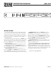
FRONT PANEL DESCRIPTION
1 SIGNAL indicators: ese green LEDs illuminate approximately 42 dB before actual clipping.
2 SENSITIVITY controls: ese rotary controls vary incoming signal levels to the A to D converter. e output signal is also
adjusted so the AVA 22d always passes signal with unity gain into 600 Ω loads. (See operating instructions.)
3 CLIP indicators: ese red LED indicators illuminate 4 dB before clipping at the A to D converter input.
4 STORE indicator: is flashing LED indicator alerts the user that the current configuration of the AVA 22d is different from the
stored configuration. e STORE LED is off when the current configuration matches the stored configuration.
5 STORE button: is pushbutton stores both channels’ current Delay configurations into the given channels’ current Memory (A
or B). e current Memory for each channel is indicated by the lit MEMORY LED for that channel.
6 LINK indicator: is green LED lights when the unit is in LINK mode. LINK mode allows stereo operation.
7 LINK button: is pushbutton toggles between LINK mode (stereo operation) and DUAL MONO operation. (See Operating
Instructions.)
8 BYPASS buttons and indicator: ese momentary push buttons toggle each channel’s hard-wired Bypass. If an LED is on, the
given channel is Bypassed and functions like a wire. If it is off the given channel is active.
9 MEMORY indicator: ese LEDs indicate the most recently recalled Memory, A or B, for the given channel. ey also indicate
the Memory that is written to when the STORE button is pressed. e MEMORY LED flashes when the current Delay value for
that channel is different than the stored value for that channel.
0 RECALL buttons: Pressing one of these pushbuttons alternately Recalls stored Memories A and B for the given channel.
q MODE buttons and indicator: ese buttons toggle the broadcast mode for the given channel, NTSC or PAL/SECAM. Each
channel contains LEDs indicating the current broadcast Mode.
w FRAMES displays: ese 2-digit displays indicate the current Delay value for the given channel. On power up this display also
shows the currently installed software revision level.
e UP/DOWN buttons: Pressing these buttons increases/decreases the amount of Delay in the given channel.
CH 2
COPIES
CH 1
EDIT
SECAM
-10 dB
V -10 dB
V
EDIT SECAM
RECALL
STORE
MEMORY
LINK
BYPASS
A B
FIELDS
PAL
NTSC
CHANNEL 1
MODE
FRAMES
AVA 22d
AUDIO / VIDEO
ALIGNMENT
DELAY
1 2
SIGNAL CLIP
dB
u
SI
GNAL
SENSITIVITY SENSITIVITY
CLIP
dB
u
0 -16
+4 -2
0
-4 -1
2
-1
60
+4 -2
0
-4 -1
2
-8 -8
RECALL
MEMORY
BYPASS
A B
FIELDS
PAL
NTSC
CHANNEL 2
MODE
FRAMES
6.5
6.5
2
31 2
1
5
3
7 8
4 6 9
1210 13 108
1312
11 9 11