
User Manual


OPERATING / SERVICE MANUAL
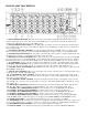
CM 86
QUICK START
Think of this like a fortune cookie: you have to read the saying before you eat it. But unlike a fortune cookie we don’t
want you to break your CM 86 before getting the message. So here’s your fortune:
Rane adheres to the AES/ANSI/IEC standards of pin 2 positive, pin 3 negative and pin 1 ground. Choose between either
the 3-pin (XLR-type) or the terminal strip MIC IN. Use only ONE; they are in parallel and do NOT sum. The LINE IN
(unbalanced 1/4") is grounded when not used. This allows the MIC/LINE switch to act as an input MUTE switch when-
ever the LINE IN jack is not used. Likewise, if it is used then the MIC/LINE switch acts like a true source selector.
Set
the rear-mounted MIC GAIN control as necessary for your mic. Use the OL indicator as an adjustment aid: increase gain
until this LED occasionally lights. Optimum noise performance results from taking as much gain as possible. (The OL indi-
cator on the front panel parallels the one on the rear.) Select PHANTOM POWER as needed for each channel indepen-
dently. When setting channel equalization, use the IN/OUT switch to compare equalized with unequalized material.
When using the AUX A/B level controls, remember to set the desired take-off location using the PRE/POST switches.
PRE takes this signal before the Channel LEVEL controls, allowing independent operation of both. POST takes this signal
after the Channel LEVEL controls, allowing the LEVEL controls to turn the Aux levels up/down simultaneously. Set the
OUTPUT SELECT to assign each input channel to the desired output. Choose between “A” only, “B” only or “AB” both.
Note that choosing only one, say “A,”
routes this input to both MASTER 1A and MASTER 2A outputs, but nothing goes
to either B output.
When setting input AUX A/B and LEVEL A/B controls, keep an eye on the appropriate PRE-OUTPUT OVERLOAD in-
dicators. They monitor overloading of the critical summing stages. Use the METER & HEADPHONE ASSIGN switch to
select the desired output for metering and monitoring. The HEADPHONE connects to the same point as the OUTPUT ME-
TERS — what you see is what you hear.
Read the Rane FLEX USERS GUIDE for details about the Flex DIN connectors. Expansion and augmentation of the CM
86 is easily done using this handy bus. TAPE OUT is taken after the MASTER INSERT LOOPS and before the MASTER
1 & 2 OUT LEVEL controls. The MASTER INSERT LOOPS do not affect the AUX A & B outputs. All four MASTER
OUTS are driven by high-current cross-coupled line drivers which will drive lines 1000 feet (305 meters) using Belden
8451 or equal wire.
Miscellaneous: The CM 86 does NOT invert signals. Use the LIFT (ground lift) switch to help eliminate stubborn hum
problems. NEVER CONNECT ANYTHING EXCEPT AN APPROVED RANE RS 2 (the big one) POWER SUPPLY
TO THE RED JACK ON THE REAR OF THE UNIT.
Good fortune and great wealth are coming your way.
SYSTEM CONNECTION
When first connecting the CM 86, LEAVE THE POWER SUPPLY FOR LAST. This gives you a chance to make mis-
takes and correct them without damaging your fragile speakers, ears and nerves.
INPUTS. Each input channel has two MIC IN connectors. The 3-pin (XLR-type) connector and the terminal strip are wired
in parallel and either one works equally well; however, they do NOT sum. USE ONLY ONE. Choose strictly from a re-
quired hardware point-of-view, there is no performance trade-off. Wiring convention conforms to the AES/ANSI/IEC stan-
dard of pin 2 positive, pin 3 negative and pin 1 ground, with the shell being tied to chassis. Microphones requiring Phantom
Powering must tie pin 1 to the shield, otherwise the Phantom Power circuit is not completed. The LINE IN is an unbalanced
1/4" jack, and may be used in conjunction with the MIC IN. The MIC/LINE switch then operates as a selector switch. When
(continues on last page...)