
Manual


Manual-3
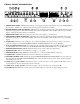
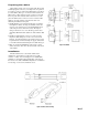
REAR PANEL DESCRIPTION
1. PHONE/LINE PAGING INPUT jack: This ¼" unbalanced TS (Tip-Sleeve) jack connects to a telephone system paging
output or any line level paging signal. Automatic ducking of the program signal occurs during paging.
2. MIC PAGING INPUT jack: This is a 3-pin balanced mic input for paging purposes. Automatic ducking of the program
input signal occurs when a page begins.
3. MIC TRIM control: This adjusts the microphone preamp initial gain, preventing possible feedback or distortion.
4. PAGING INPUTS ASSIGN switch: This switch determines which paging input can be remotely zone assigned. (See the
REMOTE ZONE ASSIGN INPUT JACK section on page Manual-4.)
5. PAGING DUCKER DEPTH control: When paging occurs, these controls set the volume of the program material. They
are adjustable from essentially off at “0” (no program sound) to about 3 dB below the paging level at “10”.
6. PROGRAM INPUT jacks 1-3: These stereo pairs of RCA connectors are line level inputs, suitable for the audio outputs of
VCRs, CD players, tape recorders, tuners, etc.
7. PROGRAM INPUT PRIORITY/4 jack: When a signal appears at this input, the CP 62 automatically switches to this input
no matter which source was selected previously. When the signal ceases, the original input slowly fades back after 35
seconds. (This option is defeatable: see LINE 4 INPUT PRIORITY INTERNAL JUMPER OPTION on page Manual-4.)
8. AUTOMATIC PRIORITY OVERRIDE ASSIGN switch: Selects at which zone the signal at the LINE 4/PRIORITY input
is heard. You may choose ZONE 1, ZONE 2 or BOTH.
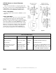
9. ZONE 1 MODE switch: Determines if zone 1 remains in stereo or if the program input left and right are summed to mono.
When ZONE 1 MODE is set to MONO, this provides two separate mono zones with the same source and EQ. Separate
levels are accessible by daisy-chaining two optional R2 remote control units for a total of three remote controllable zones
(see page Manual-5 for more information).
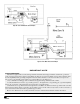
10. ZONE 1 & ZONE 2 INSERT jacks: These unbalanced, ¼" Tip=Send, Ring=Return connectors allow insertion of external
signal processors such as equalizers or compressor/limiters. Zone 1 is stereo or dual mono. If zone 1 is used as dual mono,
ZONE 1 LEFT and ZONE 1 RIGHT may use separate processing.
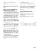
11. Balanced ZONE 1 OUTPUT jacks: These balanced ¼" TRS (Tip-Ring-Sleeve) connectors provide signal to the zone 1
amplifiers. These outputs are wired Tip = “+”, Ring = “–”, and Sleeve = ground, and should be connected to balanced
equipment whenever possible. Unbalanced ¼" TS connectors and wiring work if cable lengths are kept short (under 10 feet
to the amplifiers). Consult the included RaneNote 110 “Sound System Interconnection” for wiring conventions.
12. BALANCED ZONE 2 OUTPUT jack: This balanced ¼" TRS connector provides a mono signal to the zone 2 amplifier.
This output is electronically balanced and wired as above.
13. ZONE 1 & 2 MAXIMUM OUTPUT controls: These screwdriver trim adjustments turn down the maximum output
available to zone 1 or zone 2.
14. SOURCE & LEVEL REMOTE connectors: These modular jacks connect optional Rane R2 remotes to control program
and level in each zone.
15. REMOTE ZONE ASSIGN connector: This modular jack connects with the optional Rane R1 remote control. This
connector allows remotely assigning the zone(s) for either the MIC or PHONE/LINE, depending on the position of the rear
panel PAGING INPUTS ASSIGN switch. (See #4 above.)
16. SIGNAL GROUND LIFT switch: This switch provides the ability to separate chassis and signal ground. Normally, this
switch should be in the “grounded” position. In some circumstances, the opposite position eliminates stubborn hum and
buzz problems. Always turn your amplifier down before switching your grounds.
17. POWER input connector: This product requires a Rane RS 2 power supply. This is not a telephone jack! This calls for an
18-24 VAC center-tapped transformer. Consult the factory for replacement or substitution.
18. Chassis ground point: The CP 62 must be earth grounded. This screw allows attachment of a wire, allowing a secure
electrical connection to the chassis of the CP 62. See the CHASSIS GROUNDING note on page Manual-8 for details.