
Manual


Manual-7
Preparing the cables
All modular connectors are not created equal. The typical
modular plug that connects to your telephone is a 6-position/
4-conductor connector, named by an RJ number to describe it
(i.e. RJ11, RJ14). This type of connector will not fit into the
CP 62 remote outlets. The appropriate connector for the CP
62 is a 4-position/4-conductor, and is referred to as a “tele-
phone modular handset connector”. It does not have an RJ
number to describe it. Most companies have their own
different part numbers for this part.
1. Install standard copper stranded 28-26 guage 4 conductor
flat telephone cable to an empty electrical box where the
remote is to be located. Do not use high flexibility tinsel
cable. Strip an end to check if necessary. The ampere
rating for tinsel wire is too low, affecting system remote
reliability. Maximum cable distance from the CP 62 is 200
feet.
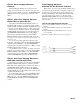
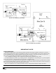
2. Install a modular handset connector on each end of the
telephone cable, taking note of wire colors as shown in
Figure 4. Special crimp hand tools and the connectors may
be purchased at commercial telephone supply outlets. This
tool is different than standard telephone modular line types.
3. Plug one end into the MAIN jack of the remote control
unit. Connect the other end to the desired jack on the back
of the CP 62.
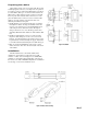
Installation
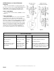
The R1 and R2 remote control units will mount in
standard U.S. electrical boxes in the same way as wall
switches or outlets, as shown in Figure 2. Use a DECORA
®
wall plate or equivalent to allow the labeling on the front of
the remote to be visible. DECORA wall plates are available in
a wide range of colors at most hardware stores.
Figure 2. Installation
Figure 4. Remote connector wiring