
User's Manual


Manual-4
OPERATING INSTRUCTIONS
A PRIMER
Let’s start with what a compressor actually does. No matter how
you cut it, this is an automatic volume control. It is a hand on
a knob, turning the volume down and turning it up again. e
hand is really quick and really accurate, but it’s just turning a
volume control.
When the input signal reaches a level set by the COMPRES-
SOR THRESHOLD control, the compressor begins turning
down the signal by an amount determined by the RATIO
control. e DC 22S, like most compressors, operates by mak-
ing the loud signals quieter, but does not make the quiet parts
louder. However, by keeping the loud signals under control, the
entire system may be turned up when necessary to make the
quiet parts louder.
PRE-FLIGHT CHECKLIST
Before proceeding, it’s a good idea to turn the control knobs to
the following positions:
1. GATE THRESHOLD control .....fully counterclockwise
2. COMPRESSOR THRESHOLD ...fully clockwise
3. COMPRESSOR RATIO ..............fully counterclockwise
4. BYPASS switches .....................ACTIVE (out)
5. OUTPUT LEVEL ........................0 dB
is renders the DC 22S with no compression, allowing sig-
nal through at unity gain. No change occurs with the BYPASS
switch in or out.
INPUT LEVEL
Before making any reshold adjustments, set the ouput level of
the previous device so the +4 dBu LED lights occasionally, and
the OL LED does not light. Be aware that changes to the Input
Level will affect the resholds.
GATE THRESHOLD
e threshold is the point at which gain adjustment begins. When
the input signal is below the threshold, the DC 22S attenuates
the signal at a 2:1 ratio, making the quiet parts twice as quiet.
When the signal is above the Gate reshold, the Gate is open,
like a straight wire.
COMPRESSOR THRESHOLD
e threshold is the point at which gain adjustment begins. When
the input signal is below the threshold, the Compressor section
acts like a straight wire. When the signal is loud enough to cross
the Compressor reshold, the compressor is active and turns
the volume down. Various reshold points are illustrated in
Figure 1. How much it gets turned down is determined by the
RATIO control ( Figure 1 shows a Ratio set at 2:1).
RATIO
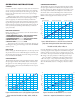
Figure 1. With a xed Ratio set to 2:1, this graph shows gain reduction
below various Gate Thresholds at -20 dBu, -30 dBu, -40 dBu, etc.
FIgure 3. Threshold at -40 dBu. Ratios of 1:1, 1.2:1, 1.5:1, etc.
Vertical axis = output level, horizontal axis = input level.
AUDIO PRECISION amp 09 AUG 101 14:51:28
-80
-70
-60
-50
-40
-30
-20
-10
0
AMPL(dBr) vs AMPL(dBu)
-80 -70 -60 -50 -40 -30 -20 -10 0
INPUT (dBu)
O
U
T
P
U
T
d
B
u
Once the reshold is exceeded, the increase in output compared
to the input signal increase depends on the RATIO setting. An
ordinary preamp set for unity gain or a straight wire has a ratio
of 1:1, that is, the output level tracks the input level perfectly. A 2
dB change at the input produces a 2 dB change at the output.
For a 10:1 Ratio, a 10 dB blast at the input would rise only
1 dB at the output – heavy compression. Kinder, gentler ratios
are in the 2:1 to 3:1 range. Limiting, with no increase in signal
above the reshold, occurs at ∞:1. Figure 3 illustrates various
Ratios.
AUDIO PRECISION 09 AUG 101 14:34:57
-60
-50
-40
-30
-20
-10
0
10
20
-40
-30
-20
-10
0
10
AMPL(dBr) VS AMPL(dBu)
-60 -50 -40 -30 -20 -10 01020
INPUT (dBu)
O
U
T
P
U
T
d
B
u
Figure 2. With the Ratio set to ∞, the DC 22S acts as a Limiter. This
graph shows Limiter gain reduction above various Compressor
Thresholds at 10 dBu, 0 dBu, -10 dBu, etc.
AUDIO PRECISION 09 AUG 101 14:45:47
-60
-50
-40
-30
-20
-10
0
10
20
AMPL(dBr) vs AMPL(dBu)
-60 -50 -40 -30 -20 -10 01020
1:1
1.2:1
1.5:1
2:1
3:1
6:1
∞:1
INPUT (dBu)
O
U
T
P
U
T
d
B
u