
Owner manual
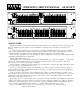
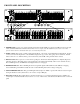

FRONT PANEL DESCRIPTION
1. POWER Switch: It comes as no surprise that this switch turns the GE 27/GE 14 on and off. An LED is located to the right
of this switch that illuminates when the unit is turned on. Each output of the GE 27/GE 14 is fitted with a relay which
provides delayed turn-on and instant turn-off to avoid switching transients.
2. LEVEL Control: This sets the overall Level through the GE 27, or the Level of each Channel through the GE 14. Use this
control to turn down the Input if the overload LED ever lights. The approximate unity gain position of the knob, with all
sliders centered is “7.5”. Full clockwise position of the knob yields 6-8dB of line gain with sliders centered.
3. BYPASS Switch: This is a passive or “hard-wired” type Bypass, which means that the Equalizer is completely Bypassed
when this switch is in. The Input jack is connected directly to the Output jack internally, with no active elements in series.
The red LED right next to the BYPASS switch lights whenever it is engaged.
4. OVERLOAD Indicator: This red LED lights whenever signal through the GE 27/GE 14 reaches 4dB below clipping.
Occasional flashing of this LED is usually safe, but consistent blinking means there is danger of clipping.
5. SIGNAL PRESENT Indicator: This green LED lights with any Input of -20dBu or greater. This indicator assists in signal
tracing should the need arise (and it will, sooner or later, so help us Murphy).
6. Filter Slider Controls: These 45mm sliders control the amount of boost or cut at the indicated frequency. All filters are
constant-Q for constant bandwidth at any level of boost or cut, on ISO centers, and calibrated in 3dB increments on the front
panel.