
Instruction Manual


Manual-6
©Rane Corporation 10802 47th Ave. W., Mukilteo WA 98275-5098 TEL 425-355-6000 FAX 425-347-7757 WEB www.rane.com
OPERATION
Voltage Controlled Attenuators
e voltage controlled attenuators (VCAs) in the MA 6S
allow a significant increase in usable volume levels without exces-
sive clipping or interference from conventional distortion causing
muting circuits. e VCAs do not affect dynamic response,
distortion or noise levels of any material within the rated output
specifications of the amplifier. ey simply monitor the differ-
ence between Input and Output signals, and the power dissi-
pated in the output devices. In the event of clipping or excessive
dissipation in the output devices, the VCAs “jump in” (out of
hiding, as it were) and turn down the Input level to correct the
overdrive condition.
is means that whenever a CLIP LIMIT flashes, a musical
peak has been quickly turned down to avoid excessive clipping.
is allows you to run the amplifier at a higher continuous level,
typically about 4 dB SPL higher than without VCAs. And that
4 dB of increased SPL is the equivalent of a 250 watt amplifier
without VCAs.
If an SOA LIMIT flashes, the Input level has been quickly
turned down to prevent over-dissipation in the output devices
due to excess phase shift or abnormally low impedances which
may occur at some frequencies. is protection occurs without
distorting or interrupting the program.
Keep an eye on the LEDs on the MA 6S front panel. Occa
-
sional flashing of a CLIP LIMIT and/or occasional flashing of a
SOA LIMIT means you are getting the most SPL out of the am-
plifier. Continual lighting of either LED indicates excessive input
overdrive, or too low impedance of load. If a green READY goes
off, a load has been encountered that could not be corrected by
the VCAs, or the amplifier has offset. If this occurs, the amplifier
must be turned off and the problem corrected before the channel
can be operated. If the READY LED will not light with the load
disconnected, then an internal fault has occurred and the ampli-
fier is in need of repair.
Adapting the MA 6S to Your Changing Needs
With six channels to choose from and built-in Bridging,
there are a number of different combinations available to suit
your present and growing needs. e nice thing about the MA
6S is that you can re-configure it instead of losing money on an
obsolete, used piece of gear you no longer need.
You can start out with 6 channels at 100 watts or three chan
-
nels at 300 watts. When the time comes, you can step up to six
channels at 300 watts by obtaining another MA 6S and keeping
the original. Upgrading to biamped monitors or tri-amped mains
becomes easy as well, by simply adding a second MA 6S, both
taking up only 10.5" rack space.
The MA 6S and Circuit Breakers
e MA6S will easily deliver over 900 watts of audio power,
requiring as much as 15 amps of current from the AC outlet. 15
amps is not an uncommon value for household and some insti
-
tutional circuitbreakers, though 20 amp versions are becoming
more common. e bottom line is that the MA 6S is capable
of tripping a 15 amp circuit breaker under normal operation. An
amp that delivers a lot of power, drinks a lot of power to do so.
It is not likely that you will trip a breaker, but it is wise to be
aware of the possibility so you don’t panic if it happens.
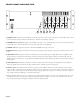
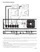
INTERNAL JUMPERS
Each amplifier card contains a jumper block that gives the
option of inserting an 80 Hz High-Pass Filter into the Input sig-
nal. is is required in 70 or 100 volt systems when excessive bass
can saturate the transformers, reduce the output, and possibly
blow a fuse at high output levels.
e MA 6S is shipped with these jumpers in the out position
(filters defeated). Moving this jumper to the in position activates
the filter.
CAUTION: WAIT ABOUT 15 MINUTES AFTER THE
AMPLIFIER HAS BEEN POWERED DOWN BEFORE
BEGINNING DISASSEMBLY, TO ALLOW THE POWER
SUPPLY CAPACITORS TO DISCHARGE.
1. Remove the bottom cover: 4 each #6 x 3/8" phillips screws
on the bottom of the side rails and 12 each #6 x 1/4" phillips
screws on the bottom cover.
2. 80 Hz High-Pass Internal Jumpers: To access the jumper
on each amplifier card, locate J2 (LOW FILTER). e MA
6S is shipped with these jumpers in the OUT position (filters
defeated). Moving this jumper to the IN position activates the
filter.
107213
In the event that 80 Hz is not a high enough cutoff frequency,
values may be changed to replace 3 resistors on each amplifier
card. is operation requires dissasembly and soldering as out-
lined in the MA 6S SERVICE INFORMATION section, and
should only be performed by qualified service personnel.