
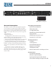
Installation guide

6
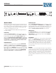
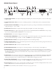
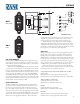
CP52S Front Panel
1 PAGING INPUT TRIM control adjusts the Page Input preamplier gain to match the microphone / source in use. e range is
30 dB to 60 dB.
2 PAGING INPUT MIC / LINE switch selects a 30 dB Input pad when set to LINE. Phantom Power is disabled when LINE is
selected.
3 PAGING DETECT THRESHOLD sets the Page signal level required to gate a Page on and illuminate the ACTIVE indicator
(see 5). e range is -∞ (on) to +4 dBu.
4 PAGING OL Overload) indicator lights when the Page Input preamplier comes within 3 dB of clipping.
5 PAGING ACTIVE indicator lights when the Page signal level reaches the PAGING DETECT THRESHOLD. A Page is always
Active when the PAGING DETECT THRESHOLD is set to minimum (ccw).
6 PAGING LEVEL control adjusts the Paging Level in the Zone.
7 PAGING LIMIT THRESHOLD control sets the maximum output level for a Page. is is a true voltage Limiter circuit with a
ratio of 15:1. e reshold range is -20 dBu to +20 dBu. e LIMIT indicator lights during limiting.
8 PROGRAM INPUT LEVELS allow independent adjustment of level for each Program Input.
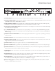
9 ZONE DUCKER DEPTH control sets the Ducker Depth (the amount of Program attenuation during a Page) from 50 dB (ccw)
to 6 dB (cw). e Ducker release is ramped.
0 ZONE DUCKER OFF / ON switch turns the Ducker ON or OFF.
q ZONE PROGRAM SELECT switch assigns one of four Program Inputs to the Zone Output, only when w is out.
w ZONE REMOTE switch, when pushed in, turns control of Zone Level and Zone Program Selection over to the Zone Remote
Port. Front panel ZONE LEVEL and ZONE PROGRAM SELECT controls are inactive when REMOTE is selected. An optional
wired ZR1 remote may be connected to the Zone Remote Port. An object smaller in diameter than the switch button is required to
engage the REMOTE switch.
e ZONE LEVEL control adjusts the overall Level for the Zone Output. If the rear panel PAGE LEVEL TRACKS ZONE LEVEL
switch is ON, this control also eects the Paging Level. ZONE SIG and OL indicators assist in setting the LEVEL control, il-
luminating with Signal present at -20 dBu and Overload at +16 dBu (4 dB before clipping) respectively.
r ZONE LIMIT THRESHOLD control sets the maximum level for the Zone Output. is is a true voltage Limiter circuit with a
ratio of 15:1. e reshold range is -20 dBu to +20 dBu. e LIMIT indicator lights during Limiting.
t Graphic Equalizer controls are “stereo,” with each slider controlling the response of both Left and Right channels. ese controls
allow ±12 dB adjustment of seven ISO center frequencies on 1
1
/
3
-octave centers.
y POWER indicator illuminates when the CP52S is connected to a proper power source.
LEVEL
4k
630
1.6k
40
100
250
PROGRAM
SELECT
OL
SIG
LIMIT
10k
PRIORITY
LIMIT
THRESHOLD
LIMIT
LEVEL
LINE 1
LINE 2
LINE 3
ACTIVE
INPUT
TRIM
OL
LINE
MIC
ON
OFF
DETECT
THRESHOLD
DUCKER
DEPTH
CP52S
COMMERCIAL
PROCESSOR
POWER
ZONE
EQ
PROGRAM INPUT LEVELS
PAGING
LIMIT
THRESHOLD
REMOTE
L1
P
L2
L3
+60+30
12
•
6
•
•
•
6
12
0
+
+8
–3
+20–20
+16
+8
–3
+20–20
+16
10
0
2
4
8
6
2
8
10
0
4
6
10
0
4
6
10
0
4
6
10
0
4
6
10
0
2
4
8
6
2
10
4 5 12 168 15
1 3 9 11 133 146