MONGOOSE Design Manual MICROPHONE MICROPHONE SIG / OL POWER MICROPHONE SIG / OL COMM AUDIO RX LINE INPUT SIG / OL AUDIO TX POWER MICROPHONE AUDIO RX MICROPHONE AUDIO RX POWER AUDIO TX AUDIO RX MICROPHONE MICROPHONE LINE OUTPUT LINE OUTPUT SIG / OL SIG / OL SIG / OL SIG / OL COMM AUDIO RX COMM AUDIO RX AUDIO RX MICROPHONE SIG / OL POWER AUDIO TX COMM MICROPHONE RAD PORT COMM LINE OUTPUT LINE OUTPUT SIG / OL SIG / OL SIG / OL AUDIO TX SIG / OL COMM LINE OUTPUT S
MONGOOSE Design Manual Contents List of Figures................................................................................................................................................. 3 SECTION 1: INTRODUCTION...................................................................................................................... 4 Purpose of this Document.........................................................................................................................
MONGOOSE Design Manual List of Figures Figure 1: Audio system using analog cables............................................................................................................................................................. 6 Figure 2: Audio system using Mongoose and RADs............................................................................................................................................. 7 Figure 3: Front panel of the Mongoose..........................................
MONGOOSE Design Manual SECTION 1: INTRODUCTION Perhaps you are familiar with the furry yet ferocious mongoose, a member of the Herpestidae family that is known for its agility and cunning – so fast and smart that it can capture venomous snakes, even king cobras. But did you know that a Rane Mongoose can perform a similar feat with your CobraNet network? Now we’re certainly not insinuating that CobraNet is venomous! In fact, we’d say just the opposite.
MONGOOSE Design Manual Rane Mongoose Documentation Set In addition to this design manual, the Rane documentation set includes an installation manual and a software help system built into the Mongoose Tracker. The Mongoose Installation Manual (available on the Rane website) explains the details of racking the Mongoose and connecting it to the network, installing the RAD devices and connecting them to the Mongoose, and troubleshooting any connection or audio problems that arise.
MONGOOSE Design Manual SECTION 2: UNDERSTANDING THE MONGOOSE SYSTEM Rane understands the pain and expense of pulling and managing miles of analog cable throughout a large audio installation, not to mention the potential for inferior sound quality. The advent and rapid adoption of digital audio networking has almost ended this cabling and quality nightmare – but not quite. You have probably utilized one or more of the networking solutions that exist today – for example, CobraNet, Ethersound, and others.
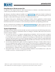
MONGOOSE Design Manual Now take a look at the difference when you replace the analog connections with a RAD network: Control Room Rack Auditorium RAD4 RAD1 MICROPHONE LINE OUTPUT MICROPHONE SIG / OL POWER LINE OUTPUT SIG / OL COMM AUDIO RX POWER AUDIO TX COMM AUDIO RX AUDIO TX RAD4 RAD1 CobraNet® DSP RAD4 RAD1 MICROPHONE MICROPHONE SIG / OL POWER LINE OUTPUT LINE OUTPUT SIG / OL COMM AUDIO RX POWER AUDIO TX COMM AUDIO RX RAD1 +6 1 +6 0 0 OFF LOW +6 4 6 0 10 2 OF
MONGOOSE Design Manual The Benefits of a Mongoose To most effectively design a system containing a RAD network, you need to understand its benefits so you can take full advantage of them. For example, when using RADs, not only can you place line-level audio and a microphone within the same conduit, you can place it on the same cable! Following is a brief discussion of how key aspects of an audio system are handled within a Mongoose system versus a typical analog system.
MONGOOSE Design Manual Simpler and Faster to Change Audio Routing In an analog system, audio is often routed by hardwiring the necessary connections. Therefore, to change the routing, you must change the wiring – often a tedious and time-consuming process. With the Mongoose system, however, the audio routing is handled by software. To change the routing, you simply point and click within the Mongoose software application. Audio routing changes are literally as simple as the click of a mouse.
MONGOOSE Design Manual The Mongoose Host Device The primary purpose of the Mongoose host device is to connect up to eight RADs to a CobraNet network. It is typically housed in the audio rack room along with the DSP and other audio equipment.
MONGOOSE Design Manual 2 The CobraNet status indicators provide information about the Mongoose’s CobraNet connection. There are two sets of indicators for each CobraNet network – Primary and Secondary. Of course, the secondary network indicators function only if you have implemented a secondary (or backup) CobraNet network. � In Use/Conductor LED (yellow) – indicates that the CobraNet port is in use, in other words CobraNet packets are being sent or received by the Mongoose.
MONGOOSE Design Manual Rear Panel Description 1 MONGOOS ONGOOSE MADE IN U.S.A. 2 3 100-240 V 50/60 Hz 40 WATTS 5 ETHERNE THERNET THIS DEVICE COMPLIES WITH PART 15 OF THE FCC RULES FOR A CLASS 'B' COMPUTING DEVICE. RANE CORP.
MONGOOSE Design Manual Mongoose Block Diagram CobraNet Primary Ethernet MAC/Phys CobraNet Hardware Chip Secondary RX 2 Bundles, 16 Channels Ethernet MAC/Phys TX 2 Bundles, 16 Channels AES3 RX (x8), 16 Channels Ethernet Remote Audio Ports 1 Remote Audio Tranceivers 2 Remote Audio Tranceivers 3 Remote Audio Tranceivers 4 Remote Audio Tranceivers 5 Remote Audio Tranceivers 6 Remote Audio Tranceivers 7 Remote Audio Tranceivers 8 Remote Audio Tranceivers AES3 TX (x8), 16 Channels 32 x 32
MONGOOSE Design Manual Remote Audio Devices The primary purpose of a Remote Audio Device (RAD) is to amplify, digitize, and transmit a digital audio signal via shielded CAT 5e cable to a Mongoose host device. RADs can also receive a digital signal from the Mongoose and then convert it to analog before sending it to its attached audio equipment. RADs are capable of transmitting and receiving up to four channels of digital audio (two in each direction).
MONGOOSE Design Manual Typical RAD Front Panel Custom Label Slot Removable Locking Tab Analog Audio Connection SIG / OL green if an audio signal is detected, red light during signal overload. POWER green when the RAD is receiving power, red if the voltage is low. COMM green if the communications pair is detected, red if there is a problem.
MONGOOSE Design Manual Typical RAD Back Panel 2 – + – + 1 1 RJ-45 (8P8C) jack for the CAT 5 cable. Figure 8: Back of a RAD 2 Euroblock connectors to use if paralleling microphone jacks (Disclaimer: As it is poor design to plug two microphones into a single microphone input, we do not recommend this practice. If, however, you have a situation that warrants it, proceed with caution. We recognize that paralleling microphone jacks can lower the cost of your audio system.) NOTE: RADs are hot-swappable.
MONGOOSE Design Manual Following is an annotated screen shot of the Mongoose Tracker’s main window: Figure 9: Mongoose Tracker main window Understanding how the Audio is Routed Understanding how the audio signal finds its way back and forth between a RAD and the host Mongoose is fairly straightforward. It’s literally a direct connection. But where does it go from there and how do you control it? Depending on your audio system, there are several options for routing a RAD audio signal.
MONGOOSE Design Manual To configure the audio routing, you use the Mongoose Tracker routing matrix. The matrix contains an area for RAD channels and an area for CobraNet channels, allowing the routing of signals directly to and from RADs and/or to and from CobraNet Bundles.
MONGOOSE Design Manual RAD to RAD routing (same Mongoose) The following graphics illustrate a simple tie-line situation – routing audio between RADs that are connected to the same Mongoose. Hardware view: RAD MICROPHONE MICROPHONE SIG / OL POWER SIG / OL COMM AUDIO RX AUDIO TX RAD1 MONGOOSE MADE IN U.S.A. MONGOOSE COMMERCIAL AUDIO EQUIPMENT 24TJ R REMOTE AUDIO DEVICES 1 LOCATE POWER RANE CORP.
MONGOOSE Design Manual RAD to RAD routing (different Mongoose) The following graphics illustrate audio routing between RADs connected to different Mongoose devices. Hardware view: RAD MICROPHONE MICROPHONE SIG / OL POWER SIG / OL COMM AUDIO RX AUDIO TX RAD1 MONGOOSE A MONGOOSE MADE IN U.S.A. MONGOOSE A COMMERCIAL AUDIO EQUIPMENT 24TJ RANE CORP. ETHERNET THIS DEVICE COMPLIES WITH PART 15 OF THE FCC RULES FOR A CLASS 'B' COMPUTING DEVICE.
MONGOOSE Design Manual Mongoose A Matrix view: Mongoose B Matrix view: Figure 15: Simple view and actual view of matrices routing signal from RAD to RAD on different Mongoose devices 21
MONGOOSE Design Manual RAD to CobraNet device The following graphics illustrate the routing of audio between a RAD channel and a CobraNet device. Hardware view: RAD MICROPHONE MICROPHONE SIG / OL POWER SIG / OL COMM AUDIO RX AUDIO TX RAD1 MONGOOSE MADE IN U.S.A. MONGOOSE Tx 425 COMMERCIAL AUDIO EQUIPMENT 24TJ RANE CORP. ETHERNET THIS DEVICE COMPLIES WITH PART 15 OF THE FCC RULES FOR A CLASS 'B' COMPUTING DEVICE.
MONGOOSE Design Manual RADs from multiple Mongoose devices to a CobraNet device The following graphics illustrate the aggregation of RAD channels from two Mongoose devices into a single CobraNet Bundle. These graphics are more complex than the previous ones, so we’ll add more explanation. In this scenario, one Mongoose transmits two RAD channels to another Mongoose via CobraNet.
MONGOOSE Design Manual Simplified Matrix view: Mongoose A Matrix view: MONGOOSE B CobraNet Bundle 301 Any CobraNet Device Rx 301 MONGOOSE A R R CobraNet Bundle 300 R R Note: In the above illustration, each line represents two channels.
MONGOOSE Design Manual SECTION 3: DESIGNING YOUR SYSTEM Now that you have reviewed the basics, you are ready to begin designing this technology into an audio system. The purpose of this chapter is to provide tips and suggestions for incorporating RADs and Mongoose devices into your design. Also included are some sample applications and representative oneline drawings. Our hope is that one of these comes close enough to your situation that you’ll have a head start with your own design.
MONGOOSE Design Manual 3. Be sure to design the routing of the CobraNet Bundles for your entire system during your planning. You’ll appreciate this when it is time to configure the Mongoose audio routing matrix! 4. For large audio systems, consider using CobraCAD software to help with your network design. CobraCAD is a software application that provides a simple graphical user interface for visualizing and designing CobraNet networks.
MONGOOSE Design Manual This graphic shows a CAT 5 scenario involving two Mongoose devices. In this situation, the maximum distance between the RADs would be 500 meters. The next graphic shows a scenario that uses both CAT 5 and fiber to connect RADs located in different buildings more than 100 meters apart.
MONGOOSE Design Manual 5. How do you plan to manage your CobraNet network? You can use the Mongoose Tracker to manage several key CobraNet settings – the CobraNet transmit and receive Bundle numbers associated with the Mongoose host device, and the routing of audio to and from the Mongoose CobraNet Bundles. If you want to view and manage other CobraNet settings not included in the Mongoose Tracker, you can do so using an SNMP MIB browser or the CobraNet Disco software.
MONGOOSE Design Manual Example Applications This section includes several example audio designs utilizing the Mongoose system. Each example includes a generic one-line audio design, a detailed floor plan incorporating the Mongoose technology, and a shop drawing (similar to the one-line drawing but with Mongoose equipment specified). Each example also includes a link to its corresponding Mongoose Tracker configuration file (on the Rane website).
MONGOOSE Design Manual Following is a floor plan of the system: Saint Dawkins Church 79th Street Overflow Hall powered speaker powered speaker assumes <150 meters between buildings Existing analog audio system LINE INPUT LINE INPUT SIG / OL POWER LINE OUTPUT AUDIO RX AUDIO TX POWER MONGOOSE R 100-240 V 50/60 Hz 40 WATTS ETHERNET THIS DEVICE COMPLIES WITH PART 15 OF THE FCC RULES FOR A CLASS 'B' COMPUTING DEVICE. COMMERCIAL AUDIO EQUIPMENT 24TJ RANE CORP.
MONGOOSE Design Manual The Mongoose configuration file for this example application can be downloaded here: saint_dawkins. mgs.
MONGOOSE Design Manual RAD to DSP (or other device) via CobraNet using a Single Mongoose Since we can safely assume that you’ve been inside an elementary school at some point in your life, we can also assume that you are familiar with those funny room combinations called “cafetoriums” – a lunch room and auditorium rolled into one. The following sample application illustrates a possible Mongoose system that would serve such a space.
MONGOOSE Design Manual Following is the floor plan for the system: powered speaker powered speaker RAD4 mounted high on wall, near powered speaker, stage left Stage Left LINE OUTPUT Mic 1 Mic 2 MICROPHONE LINE OUTPUT COMM AUDIO RX AUDIO TX POWER Mic 3 MICROPHONE SIG / OL POWER RAD4 mounted high on wall, near powered speaker, stage right RAD1s for stage mics mounted on sides or back of stage MICROPHONE SIG / OL COMM AUDIO RX Mic 4 SIG / OL AUDIO TX POWER MONGOOSE MADE IN U.S.A.
MONGOOSE Design Manual Here is the corresponding shop drawing: RAD1 MIC INPUTS Stage Back RAD1 MIC INPUTS Stage Left Powered RAD4 LINE OUTPUTS RAD2 MIC / LINE INPUTS Stage Right MONGOOSE RAD4 LINE OUTPUTS Powered Rx 395 Tx 486 ETHERNET SWITCH Rx 486 Tx 395 RAD network (CAT 5) Cobranet network (CAT 5) Audio cable (XLR) COBRANET AUTO-MIXER Figure 31: Shop drawing for cafetorium example application (illustrating RAD to DSP routing) The Mongoose configuration file for this example application can
MONGOOSE Design Manual RAD to DSP (or other device) using Multiple Mongoose Devices The following sample application is a bit more complex. It is a hotel that contains several meeting rooms, a ballroom, and a restaurant/bar. It is a prime target for the Mongoose because of the low channel count in each room and the scattered locations of each audio input and output. This system requires more than eight RADs and, therefore, requires more than one Mongoose.
MONGOOSE Design Manual Following is the one-line drawing for this audio system: Bar Inputs Atilax Room Inputs Restaurant Inputs Cusimance Room Inputs Meerkat Room Inputs E Mic E Mic E Mic E Mic E Mic E Mic NW Mic NW Line SE Mic SE Line N Mic N Mic S Mic S Mic W Mic W Mic W Mic W Line Satellite Jukebox TV DVD DSP 70V 70V Powered speaker in each corner Powered speaker in NE and SW corner Powered speakers on sides and back Figure 33: One-line drawing for hotel example application
REMOTE AUDIO DEVICES 1 1 2 2 1 2 1 2 3 1 2 1 2 4 1 2 1 2 5 1 2 1 2 6 1 2 1 2 7 1 2 1 2 8 1 2 1 2 DATA CONDUIT ETHERNET CobraNet 1 2 MONGOOSE OVERLOAD SIGNAL IN USE / CONDUCTOR ENABLED LINK / ACTIVITY IN OUT IN OUT IN OUT IN OUT IN OUT IN OUT IN OUT IN OUT PRIMARY COMM LOCATE LINK POWER North Remote Audio CobraNet Interface East SECONDARY DATA CONDUIT Portable Rane AM 1 Automixer on A/V Cart RAD PORT RADX CobraNet® DSP MIC INPUTS 2 3 1 MI
MONGOOSE Design Manual Here is the corresponding shop drawing: Meerkat Room Inputs Cusimance Room Inputs MLM 42S MIXER Powered Speakers Powered Speakers RAD MIC INPUTS RAD LINE INPUTS RAD LINE OUTPUTS RAD LINE OUTPUTS RAD MIC LINE INPUTS RAD MIC LINE INPUTS RAD LINE OUTPUTS RAD LINE OUTPUTS MONGOOSE A Rx 378, Tx 478 COBRANET DSP COBRANET NETWORK AMPLIFIER 70V DISTRIBUTION TO RESTAURANT & BAR Analog Audio (XLR) * * RAD network (CAT5) Cobranet network (CAT 5) Rx 350, Tx 450 MONGOOSE B RAD
MONGOOSE Design Manual This example uses two Mongoose devices and, therefore, requires two configuration files. The files can be downloaded here: atilax_hotel_a.mgs and atilax_hotel_b.mgs.
MONGOOSE Design Manual Figure 37: Configuration for Mongoose B in Atilax Hotel example application (routing RADs from multiple Mongoose devices to and from one or more CobraNet devices) 40
MONGOOSE Design Manual CobraNet Bundle to CobraNet Bundle The final example application illustrates the benefits of the Mongoose’s ability to aggregate audio channels. In this example, we move to the campus of a small college – Kipling College. To help focus, we highlight a small portion of what would likely be a much larger audio system. The college has just built a new student union building (the Rudyard Student Union) and student cafeteria (the Rikki-Tikki-Tavi Cafeteria).
MONGOOSE Design Manual To handle these requirements, the contractor decides to use two DSP boxes – one handles the eight incoming music and television signals while the other handles the microphone mixing and zone processing. Inputs to the zone processing/microphone mixing DSP box are limited to two CobraNet Bundles. One of these Bundles is used for receipt of the music/television channels. This leaves only one Bundle for receipt of the microphone signals from both the student union and the cafeteria.
MONGOOSE Design Manual Here is the corresponding shop drawing: FIBER OPTIC ACROSS CAMPUS Rudyard Student Union Rikki-Tikki-Tavi Cafeteria Powered Speakers Powered Speakers RAD1 MIC INPUTS ETHERNET SWITCH RAD4 LINE OUTPUTS RAD1 MIC INPUTS Rx 340 Tx 410 RAD4 LINE OUTPUTS Rx 410 Tx 340 UNION MONGOOSE A COBRANET AUTO-MIXER DSP ETHERNET SWITCH CAFETERIA MONGOOSE B Rx 410 Analog Audio (XLR) Fiber Optic COBRANET MUSIC SELECTION DSP Ethernet (CAT 5) RAD network (CAT 5) Cobranet network (CAT 5) Figu
MONGOOSE Design Manual Figure 41: Configuration for Mongoose A in Rudyard Student Union of Kipling College 44 Figure 42: Configuration for Mongoose B in Rikki-Tikki-Tavi Cafeteria of Kipling College
MONGOOSE Design Manual SECTION 4: INSTALLATION AND CONFIGURATION ISSUES This section discusses general installation issues you may consider prior to handing your design over to the installer. The actual details of installing the product are covered in the Mongoose Installation Guide. Key Installation Tasks and Recommended Work Flow Presented below (in the recommended order) are the six primary tasks involved in installing a Mongoose system (once the initial system design is complete): 1.
MONGOOSE Design Manual Figure 43: Adjusting RAD to make it flush with wall 5. Perform an audio test. Verify the system is performing as it should. (Monitor the Signal and Overload LEDs as an indicator that the RADs are successfully receiving the audio signal. Troubleshoot any problems. If there is a problem, one of the first things to examine is the device’s audio routing matrix (in the Mongoose Tracker). The Mongoose Installation Manual includes detailed troubleshooting tips. 6.
MONGOOSE Design Manual Connecting the Mongoose to a Network – Best Practices As previously mentioned, the Mongoose connects to two types of networks – a control network and a CobraNet network. Both networks use Ethernet, but one sends and receives control data while the other sends and receives audio data. Each of these networks is described in detail below, along with recommendations for designing and implementing the networks.
MONGOOSE Design Manual About the CobraNet Network The CobraNet network is needed for transmission and reception of audio data between the Mongoose and other audio processing equipment. You use the CobraNet port to provide a network path for audio data to and from the Mongoose. There are two CobraNet ports on the back of the Mongoose – Primary and Secondary. Use the Primary port for your main CobraNet network. Use the Secondary port only if your system includes a backup CobraNet network.
MONGOOSE Design Manual Designing Each Network The complexity of your design for both networks depends completely on your situation. This section provides an overview of some typical approaches as well as recommendations for which approach to take given certain circumstances. We highly recommend separating the control network and CobraNet network. Both networks offer similar design options, listed below. You can mix and match these options as you see fit. 1.
MONGOOSE Design Manual 2. Isolated network for audio equipment This approach is often appropriate for small to mid-sized systems or for any size system that does not need to use an existing corporate network. Control Network If you need to manage multiple devices (multiple Mongoose devices and/or other Ethernetcontrolled equipment), you may want to connect all the devices to an isolated network switch.
MONGOOSE Design Manual CobraNet Network If you are creating a new CobraNet network, you’ll need to connect all your CobraNet devices to a network switch dedicated to the CobraNet network. If there is an existing CobraNet network, you will likely want to integrate the Mongoose system into it. To do so, just connect the Mongoose devices to the current CobraNet network switch.
MONGOOSE Design Manual 3. Integrate control network with existing corporate data network If a corporate network is available, you may want to consider taking advantage of its infrastructure. This approach is for the control network only, as it is very rare that you would integrate your CobraNet network with the network that carries corporate data.
MONGOOSE Design Manual 4. Use existing network hardware, but isolate the CobraNet and/or control network As described in the previous section, there are many advantages to integrating the Mongoose control network with an existing network. Since the CobraNet and the control networks use Ethernet and are compatible, it is also possible to integrate the control network and the CobraNet network.
MONGOOSE Design Manual SECTION 5: INSTALLING AND USING THE MONGOOSE TRACKER If you’ve read everything up to this point, you know by now that we highly recommend creating the Mongoose configuration file during the design phase. You’ll need the Mongoose software for this task, but you do not need any of the hardware. This section explains how to obtain, install, and start the software. It also provides an overview of what’s involved in the creation of a configuration file.
MONGOOSE Design Manual Starting Mongoose Tracker 1. On the Start menu, point to All Programs > Rane Corporation > Mongoose Tracker. 2.
MONGOOSE Design Manual Working with Configuration Files For the Mongoose system to function properly, you must configure both the Mongoose and the RADs. You configure such things as the audio routing, specific details for each connected RAD, and settings for the Mongoose and the CobraNet network. The configuration settings are described in detail in the Mongoose Tracker help system. There are two ways to configure the Mongoose and RAD devices: 1.
MONGOOSE Design Manual Distinguishing Between Live Device Settings Versus Configuration File Settings When you first open Mongoose Tracker, it displays an empty configuration screen. At this point, you can create a configuration, view or edit the contents of an existing configuration file, or – if the hardware is available and connected – view or alter the configuration of a specific live Mongoose. It is important to always be aware of whether you are working with a configuration file or with a live device.
MONGOOSE Design Manual configuration file within a single installation, but your installer may need to modify the audio routing matrix on each device. Make sure you provide this information to your installer. Creating the Configuration File The software help system provides the details on how to actually create the Mongoose configuration file. Here we will merely provide a few design tips and point out some key things to remember when working with configuration files.
MONGOOSE Design Manual create the configuration file and attach them to the physical RADs (if they are available). If you label the RADs early in the process, it may help the installers confirm they are installing the right RADs in the right places. Note: If you do not need custom labels, you can use the generic labels shipped with the RADs. To generate RAD labels: 1. Within the Mongoose Tracker, open the configuration file from which you want to generate labels.
MONGOOSE Design Manual Updating (or Rolling Back) the Mongoose Firmware The Mongoose and the RADs contain firmware that controls the functionality of the hardware and allows communication between the hardware and the Mongoose Tracker. It is important to verify that the firmware version on your hardware is compatible with the version of Mongoose Tracker that you are using. If they are not compatible, the system will not work. To determine if you need to update the Mongoose firmware: 1.
MONGOOSE Design Manual To determine if you need to update your Mongoose Tracker software, do one of the following: • By default, when Mongoose Tracker starts, it checks for the availability of updates to the software (if an Internet connection is present). If an update is available, Mongoose Tracker displays a link you can use to launch the update. You can disable this functionality (checking for updates on startup) within the Application Settings dialog box.
MONGOOSE Design Manual Index A Control network defined..................................................................................28 direct connection...............................................................48 integrated with corporate network.................................52 isolated.................................................................................49 overview...............................................................................47 use of IP addresses..................
MONGOOSE Design Manual M Network design......................................................................28 direct connection...............................................................48 integrated control/corporate network...........................52 isolated network.................................................................50 maximum hops...................................................................26 using VLANs.......................................................................
MONGOOSE Design Manual ©Rane Corporation 10802 47th Ave. W., Mukilteo WA 98275-5000 USA TEL 425-355-6000 FAX 425-347-7757 WEB rane.