
Manual

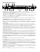

FRONT PANEL DESCRIPTION
1. BYPASS. Pressing this button toggles between Bypass and Active modes (LED on = BYPASS).
2. CURVE WEIGHT. The CURVE WEIGHT button weights curves; hammers let you hammer things and wrenches let you
wrench things. See the MPE Users Guide for details on summing two curves together.
3. STORE. Pressing this control transfers the contents of Working Memory into Stored Memory at a location selected by either
the number keys or the UP/DOWN buttons. Pressing STORE once prompts the user for the Stored Memory location;
pressing it again writes the information to Stored Memory.
4. OL. Overload (OL) indicator. This red LED illuminates any time the input, filters or output reaches 4dB below clipping.
5. EQUALIZER Display. This numeric green LED display indicates the boost/cut level of an individual filter, or the overall
Level, whichever is selected (LED on). The MPE 28 must be in the EQ Edit mode to activate this display.
6. EQ. Pressing this button once places the MPE 28 in the lower frequency EQ Edit mode (yellow LED on); a second depres-
sion enters the upper frequency EQ Edit mode (green LED on); and a third time takes the MPE 28 out of the EQ Edit mode
(both LEDs off).
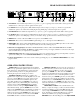
7. LEVEL / EXPRESS. In the EQ Edit mode, this button sets the overall level of the equalizer. When not in the EQ Edit
mode, this button sets Expression parameters. Expression allows an EQ curve to “bend” (change) based on MIDI continuous
controller or channel pressure aftertouch commands. Please see the MPE Users Guide for further information.
8. 31.5Hz / 800Hz / BANK. In the EQ Edit mode, this button selects either the 31.5Hz or the 800 Hz filter. In the Normal
Operating mode, pressing this control locks the MPE to the current bank; something similiar to a “tens hold” function. When
using the octal numerical base system of notation instead of the decimal numerical base (explained in the MPE Users
Guide) it has a similar function.
9. 40Hz / 1kHz / 100 / OCTAL A/B. In the EQ Edit mode, this button selects either the 40Hz or the 1kHz filter. In the Normal
Operating mode this gets you directly to the 100s, or switches between A/B banks when using the octal numerical base.
10. 50Hz / 1.25kHz to 500Hz/12.5kHz. In the EQ Edit mode, these buttons select the filters associated with their labels. In the
Normal Operating mode they allow direct access number entry for Stored Memory selection. They also select several
secondary features when used with the FUNCTION button. To find out about their uses, please see the MPE Users Guide.
11. 630 / 16kHz / FUNCTION. In the EQ Edit mode, this button selects either the 630Hz or the 16kHz filter. In the Normal
Operating mode it acts as a shift-key to select the secondary features. Again we must reference the MPE Users Guide for
details. Sorry.
12. UP & DOWN. Used to increase or decrease parameters in all operating modes.
13. SYSTEM Display. This red digital display indicates system information, such as Stored Memory locations, MIDI Channel
selection, mapping assignments, lockout codes, Factory preset numbers, ramp step size, revision number, and so on.
14. MEMORY. Used to enter the Normal Operating mode. A flashing LED indicates Working Memory differs from Stored
Memory. When in the EQ Edit mode, all changes to the Working Memory are compared with the Stored Memory version by
simply pressing and holding the MEMORY button. What is heard is the Stored Memory curve; releasing the MEMORY
button allows you to hear edited Working Memory.
15. CHANNEL. Pressing this button displays the current MIDI Channel assignment for this MPE. Flashing indicates MIDI
OMNI mode is on. Change the MIDI Channel by using the UP/DOWN buttons, or number keys. Pressing this button again
returns the unit to Normal Operating mode.
16. MAP. Used for MIDI Mapping (re-routing program changes to memory locations) covered in the MPE Users Guide.