
Manual


All features & specifications subject to change without notice. 520-259 MAY94
©Rane Corporation 10802 47th Avenue West, Mukilteo WA 98275-5098 TEL(206) 355-6000 FAX(206) 347-7757
display indicating a compare function is being performed.
While the MEMORY button is held, what is heard is the
Stored Memory curve—releasing the MEMORY button
allows you to hear the edited Working Memory version.
USING STORED CURVES. To use any of the curves in
Stored Memory, all you do is show the Stored Memory
location on the red SYSTEM display. Whatever number
shows is the label of the Stored Memory location for the
current Working Memory.
Working Memory is the scratch pad where you work. You
can think of it as the 129th memory location (like the 19th
hole in golf), except you cannot actually store anything
here—only operate on it, or listen to it. When a Stored
Memory location shows up on the SYSTEM display, the
curve is actually in two locations: safely stored at the memory
location shown and in the Working Memory scratch pad,
ready for you to change if you want. You can do anything
you want to the Working Memory without altering the
original stored version. When complete, you must store this
new version either in place of the old curve, or into a new
location. This is the significance of the MEMORY light
blinking. Once you do anything to the original curve, the
MEMORY light starts blinking to remind you that you have
changed it.
If you want a different curve, press the UP/DOWN
buttons to scroll, or directly enter a number via buttons 0
through 9 (observe the red SYSTEM display). Please note
that all Stored Memory numbers must be at least two digits;
e.g., Stored Memory number 4 is entered as 04, etc. For
direct access to Stored Memory locations above 99, push the
100 button, then the next two digits. For example, to recall
stored memory 125, press 100, 2 and 5. Once the last digit
is entered, the program is instantly called up (what you see is
what you hear). What could be simpler?
BYPASS MODE. Pressing the BYPASS button causes all
audio in the unit to be routed around the equalizer electronics.
Please note that a bypassed condition cannot be stored. If
recalling a flat curve is required, simply store a program in
which all filter and level controls are set to zero (Factory
Preset1, if it has not been overwritten in Stored Memory).
MIDI CHANNEL. Pressing the CHANNEL button
displays the currently assigned MIDI Channel. Pressing UP/
DOWN increases or decreases the MIDI Channel number.
You may select from1 through16, orOFF.
MIDI CONTROL. The MPE 28 can be controlled by
another MPE, an RPS 4 Remote Program Switch (contact
closure to MIDI Program Change converter), personal
computer, or any device capable of transmitting MIDI. A
DOS program is available from the factory by request. Details
are, you guessed it, in the MPE Users Guide.
OTHER FEATURES. To say the MPE 28 does a lot
more than explained in this brief space is like saying a
personal computer makes a good paperweight. Please read the
MPE Users Guide for a more in-depth look at your MPE 28.
FCC & VDE NOTICE
This equipment has been tested and found to comply
with the limits for a Class A digital device, pursuant to
Part 15 of the FCC Rules, and similar requirements found
in European specifications VDE 0871/0875. These limits
are designed to provide reasonable protection against
harmful interference when the equipment is operated in a
commercial environment. This equipment generates, uses,
and can radiate radio frequency energy and, if not
installed and used in accordance with the instruction
manual, may cause harmful interference to radio commu-
nications. Operation of this equipment in a residential area
is likely to cause harmful interference in which case the
user will be required to correct the interference at their
own expense. USE OF SHIELDED MIDI CABLES IS
REQUIRED FOR FCC COMPLIANCE.
CHASSIS GROUNDING
The unit is shipped with its Ground Lift switch in the
CHASSIS GND position. This ties signal ground to
chassis ground. If after hooking up your system it exhibits
excessive hum or buzzing, there is an incompatibility in
the grounding configuration between units. Here are some
things to try:
1. Try combinations of lifting grounds on units
supplied with Ground Lift switches (or links).
2. Verify all chassis are tied to a good earth ground.
3. Units with outboard power supplies do not ground
the chassis through the line cord. Make sure these units
are solidly grounded by tying the Chassis Ground Point to
known earth ground (such as a power amplifier chassis).
Use a star washer to guarantee proper contact.
IMPORTANT NOTE
POWER SUPPLY. As noted elsewhere in this manual,
NEVER USE A POWER SUPPLY WITH YOUR MPE 28
OTHER THAN THE ONE SUPPLIED FROM THE FACTORY
OR AN EXACT REPLACEMENT OBTAINED FROM RANE
CORPORATION. The MPE 28’s power supply input is
designed for an AC supply, delivering 18-24 volts, from a
center-tapped transformer capable of supplying at least the
current demanded by this product. Using any other type of
supply may damage the equalizer and void the warranty
(which at two years parts and labor is worth safeguarding,
don’t you think?).
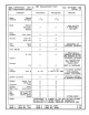
Additional information and full technical specifications
will be found on the enclosed MPE 28 Data Sheet.
SOFTWARE UPDATES
Please fill out and mail in the enclosed registration card.
Notification of any software revisions will be mailed to all
registered users. Failure to register could result in missing
important update information.