MS1S MIC STAGE Contents FCC Statement Important Safety Instructions Features General Description Application Information Features and Specifications Block Diagram Architectural Specifications Unit Dimensions Sound System Interconnection Schematic Warranty Declaration of Conformity 21591 2 3 6 6 7 9 10 10 11 12 28 31 34
FCC Statement NOTE: This equipment has been tested and found to comply with the limits for a Class B digital device, pursuant to part 15 of the FCC Rules. These limits are designed to provide reasonable protection against harmful interference in a residential installation. This equipment generates, uses and can radiate radio frequency energy and, if not installed and used in accordance with the instructions, may cause harmful interference to radio communications.
Important Safety Instructions 1. Read these instructions. 2. Keep these instructions. 3. Heed all warnings. 4. Follow all instructions. 5. Do not use this apparatus near water. 6. Clean only with a dry cloth. 7. Do not block any ventilation openings. Install in accordance with manufacturer’s instructions. 8. Do not install near any heat sources such as radiators, registers, stoves, or other apparatus (including amplifiers) that produce heat. 9.
FCC REMARQUE: Cet équipement a été testé et approuvé conforme aux limites pour un appareil numérique de classe B, conformément au chapitre 15 des règles de la FCC. Ces limites sont établis pour fournir une protection raisonnable contre tout risque d’interférences et peuvent provoquer une énergie de radiofréquence s'il n'est pas installé et utilisé conformément aux instructions, peut également provoquer des interférences aux niveaux des équipements de communication.
INSTRUCTIONS DE SÉCURITÉ 1. Lisez ces instructions. 2. Gardez précieusement ces instructions. 3. Respectez les avertissements. 4. Suivez toutes les instructions. 5. Ne pas utiliser près d’une source d’eau. 6. Ne nettoyer qu’avec un chiffon doux. 7. N’obstruer aucune évacuation d’air. Effectuez l’installation en suivant les instructions du fabricant. 8. Ne pas disposer près d’une source de chaleur, c-à-d tout appareil produisant de la chaleur sans exception. 9. Ne pas modifier le cordon d’alimentation.
MS1S MIC STAGE Features • • • • -127 dB Equivalent Input Noise Gain Control Signal / Overload Indicator Polarity Switch • • • • Switchable 48 V Phantom Power True Differential Input Cross-coupled Line Driver Internal 100-240 VAC Power Supply General Description The Rane MS1S Mic Stage preamplifier provides the answer when you need just one microphone input in an otherwise line-level world.
Application Information Uses and applications for the MS1S should be obvious. But then again, it’s obvious to us our taxes are too high and nothing is being done about that. With this in mind, perhaps a few words on using the MS1S might not be wasted. BALANCED USE The MS1S provides a true cross-coupled balanced output. This is equivalent to an electronic simulation of a transformer output. Rane follows the AES standard of pin 2 = hot.
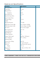
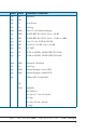
Features and Specifications Parameter Specification Input Impedance 2k Gain Range 15 to 60 Phantom Power +48 ..........Impedance 6.81k Max. Input Level +9 / -35 Equivalent Input Noise -127 Signal to Noise Ratio 94 Dynamic Range 114 / 91 CMRR 80 Frequency Response 3 to 200k THD+Noise (gain 60 dB) .004 (Output=+20 dBu) THD+Noise (gain 15 dB) .0006 (Output=+20 dBu) Line Driver Active Cross-coupled Max.
Limit Units Conditions/Comments 1% Ω Balanced typ. dB 4% V 10 mA max. 1% Ω Each leg min. dBu Gain 15 / 60, balanced output typ. dBu 20 kHz BW, Rs=150 Ω, Gain = 60 dB typ. dB 20 kHz BW, Rs=150 Ω, Gain = 15 dB, re 4 dBu typ. dB Gain 15 / 60, 20 Hz to 20 kHz typ. dB Rs=150 Ω, 120 Hz, Gain = 60 dB typ. Hz +0, -3dB typ. % 55 Hz to 20 kHz, 20 kHz BW, Rl=10 kΩ typ. % 50 Hz to 20 kHz, 20 kHz BW, Rl=10 kΩ min. dBu Balanced, 2 kΩ load 1% Ω Each Leg typ.
Block Diagram +48V PHANTOM POWER SIGNAL / OVERLOAD INVERT MIC INPUT 2 3 1 RFI +6 dB FILTER 2 1 LINE LEVEL 3 OUT GAIN 12-60 dB Architectural Specifications The microphone preamplifier shall be a single channel stand-alone unit with a removable IEC power cord. The unit shall accept voltages from 100 to 240 VAC. The input and output shall be fitted with XLR connectors. A polarity inverting switch shall be included.
Unit Dimensions 6.1" 6 8 MIN MS1S ON MAX 1.636" 4 2 MIC STAGE GAIN SIG OL 48V PHANTOM POWER 2.5" 4.225" 4.26" 0.775" 0.15" .7" 0.35" 6.8" 100-240 V 50/60 Hz 3 WATTS MS1S NORMAL POWER PIN 2: (+) PIN 3: (–) PIN 1: MADE IN U.S.A. RANE CORP.
RaneNote Sound System Interconnection • Cause & prevention of ground loops • Interfacing balanced & unbalanced • Proper pin connections and wiring • Chassis ground vs.
Introduction This note, originally written in 1985, continues to be one of our most useful references. It’s popularity stems from the continual and perpetual difficulty of hooking up audio equipment without suffering through all sorts of bizarre noises, hums, buzzes, whistles, etc.— not to mention the extreme financial, physical and psychological price. As technology progresses it is inevitable that electronic equipment and its wiring should be subject to constant improvement.
Ground Loops Almost all cases of noise can be traced directly to ground loops, grounding or lack thereof. It is important to understand the mechanism that causes grounding noise in order to effectively eliminate it. Each component of a sound system produces its own ground internally. This ground is usually called the audio signal ground. Connecting devices together with the interconnecting cables can tie the signal grounds of the two units together in one place through the conductors in the cable.
The Absolute Best Right Way To Do It The method specified by AES48 is to use balanced lines and tie the cable shield to the metal chassis (right where it enters the chassis) at both ends of the cable. A balanced line requires three separate conductors, two of which are signal (+ and –) and one shield (see Figure 1a). The shield serves to guard the sensitive audio lines from interference. Only by using balanced line interconnects can you guarantee (yes, guarantee) hum-free results.
CHASSIS GROUND R S T MALE RED BLACK SHIELD FEMALE RED 2 BLACK 3 C 3 SHIELD 1 1 2 G – + BALANCED OUTPUTS 16 RED BLACK SHIELD RED BLACK SHIELD Figure 1a. The right way to do it.
COMMON (WRONG) PRACTICE (+) CASE RECOMMENDED PRACTICE (+) CASE OPTIONAL 2 2 (–) 3 3 1 CHASSIS GROUND (–) 1 SIGNAL GROUND CHASSIS GROUND CHASSIS GROUND Figure 1b. Recommmended practice. The Next Best Right Way To Do It The quickest, quietest and most foolproof method to connect balanced and unbalanced is to transformer isolate all unbalanced connections. See Figure 2. Many manufacturers provide several tools for this task, including Rane.
The Last Best Right Way To Do It If transformer isolation is not an option, special cable assemblies are a last resort. The key here is to prevent the shield currents from flowing into a unit whose grounding scheme creates ground loops (hum) in the audio path (i.e., most audio equipment). It is true that connecting both ends of the shield is theoretically the best way to interconnect equipment –though this assumes the interconnected equipment is internally grounded properly.
See Figure 4 for suggested cable assemblies for your particular interconnection needs. Find the appropriate output configuration (down the left side) and then match this with the correct input configuration (across the top of the page.) Then refer to the following pages for a recommended wiring diagram. Ground Lifts Many units come equipped with ground lift switches. In only a few cases can it be shown that a ground lift switch improves ground related noise.
Floating, Pseudo, and Quasi-Balancing During inspection, you may run across a ¼" output called floating unbalanced, sometimes also called psuedo-balanced or quasi-balanced. In this configuration, the sleeve of the output stage is not connected inside the unit and the ring is connected (usually through a small resistor) to the audio signal ground. This allows the tip and ring to “appear” as an equal impedance, notquite balanced output stage, even though the output circuitry is unbalanced.
References 1. Neil A. Muncy, “Noise Susceptibility in Analog and Digital Signal Processing Systems,” presented at the 97th AES Convention of Audio Engineering Society in San Francisco, CA, Nov. 1994. 2. Grounding, Shielding, and Interconnections in Analog & Digital Signal Processing Systems: Understanding the Basics; Workshops designed and presented by Neil Muncy and Cal Perkins, at the 97th AES Convention of Audio Engineering Society in San Francisco, CA, Nov. 1994. 3.
From Output 22 From Output ¼” FLOATING UNBALANCED ¼” BALANCED TRS (EITHER A TRANSFORMER OR A CROSS-COUPLED OUTPUT STAGE) ¼” BALANCED TRS (NOT A TRANSFORMER, NOR A CROSS-COUPLED OUTPUT STAGE) FEMALE BALANCED XLR (EITHER A TRANSFORMER OR A CROSS-COUPLED OUTPUT STAGE) FEMALE BALANCED XLR (NOT A TRANSFORMER, NOR A CROSS-COUPLED OUTPUT STAGE) CABLE CONNECTORS 8 22 7 21 A 8 7 A 2 2 1 1 ¼" BALANCED TRS (TIP-RING-SLEEVE) MALE BALANCED XLR 11 11 B 9 5 B 3 ¼" OR 3.
From Output 23 From Output BALANCED EUROBLOCK UNBALANCED RCA (TIP-SLEEVE) ¼” OR 3.
From Output Output 24 6 T=RED RED FEMALE 1=SHIELD RED 2 2-CONDUCTOR SHIELDED CABLE BLACK 2=RED C 3 SHIELD 3=BLACK 1 CROSS-COUPLED OUTPUT ONLY: CONNECT PIN 1 TO PIN 3 AT THIS END AND SET GROUND LIFT SWITCH TO ‘GROUNDED’ (IF PRESENT). FEMALE 1=SHIELD RED 2 2-CONDUCTOR SHIELDED CABLE 2=RED BLACK C 3 3=BLACK SHIELD 1 CROSS-COUPLED OUTPUT ONLY: CONNECT PIN 1 TO PIN 3 AT THIS END AND SET GROUND LIFT SWITCH TO ‘GROUNDED’ (IF PRESENT).
From O T=RED R=NC S=SHIELD 9B RED BLACK SHIELD T=RED R=BLACK S=SHIELD T=RED R=BLACK S=SHIELD 11 12 2-CONDUCTOR SHIELDED CABLE 1-CONDUCTOR SHIELDED CABLE 1-CONDUCTOR SHIELDED CABLE 2-CONDUCTOR SHIELDED CABLE 2-CONDUCTOR SHIELDED CABLE RED BLACK SHIELD RED RED BLACK N/C SHIELD RED RED BLACK N/C RED RED 2-CONDUCTOR SHIELDED CABLE BLACK BLACK SHIELD CROSS-COUPLED OUTPUT ONLY: CONNECT RING TO SLEEVE AT THIS END AND SET GROUND LIFT SWITCH TO ‘GROUNDED’ (IF PRESENT).
From Output m Output 26 18 17 16A 15A 14 13 T=RED S=BLACK T=RED S=BLACK T=RED S=SHIELD T=RED S=SHIELD T=RED S=BLACK T=RED S=BLACK 2-CONDUCTOR SHIELDED CABLE 2-CONDUCTOR SHIELDED CABLE RED BLACK 1-CONDUCTOR SHIELDED CABLE RED BLACK SHIELD RED SHIELD 1-CONDUCTOR SHIELDED CABLE 2-CONDUCTOR SHIELDED CABLE RED BLACK N/C RED 2-CONDUCTOR SHIELDED CABLE RED BLACK SHIELD SHIELD RED RED BLACK SHIELD RED BLACK SHIELD SHIELD RED RED BLACK SHIELD MALE MALE 1 2 3 T=RED R=BLACK S=S
24 23 – + RED BLACK SHIELD 2-CONDUCTOR SHIELDED CABLE 2-CONDUCTOR SHIELDED CABLE 2-CONDUCTOR SHIELDED CABLE 2-CONDUCTOR SHIELDED CABLE 1-CONDUCTOR SHIELDED CABLE 1-CONDUCTOR SHIELDED CABLE RED RED BLACK SHIELD SHIELD RED MALE 1 2 3 T=RED R=BLACK S=SHIELD 1=SHIELD 2=RED 3=BLACK T=RED S=SHIELD (CHECK: NO STANDARD POLARITY ON EUROBLOCKS) RED + BLACK SHIELD – RED BLACK SHIELD SHIELD T=RED S=SHIELD RED (ANY UNBALANCED CONNECTOR) T=RED BLACK S=BLACK CROSS-COUPLED OUTPUT ONLY: CONNECT BLACK
Schematic UN-USED R1C 2kRD 6 5 6 4 R1B 2kRD U2B 5 GND 7 072 GND PHANTOM POWER 2.00k RED GND +12 GND Z2 + 1SMB51CAT3 GND R1A 2kRD GND 2 U1 1512 13 R16 5.10 R18 1 GAIN R14 10.0k 5 + 3 G1 8 C5 0.0033 GND C7 2200pF D10 GND 2 47/50v 22.0 R15 2.67k g=0.5 + (5k/Rg) D6 MBRS3100 V12 V+ 4 G2 - 47/50v 22.0 C6 0.0033 GND D14 MBRS3100 +12 R17 10.0k D13 MBRS3100 +12 C9 -12 GND 0.1 F3 P1 T 1A 250V 27.
-12 6 R2 10.0k U4B 5 R5 5817 2 R7 C1 + 100k 1/50v GND GND 3 R9 51.1 OL +12 D3 R6 1 U4A 4 10.0k 8 D2 RED 5.11k 072 R4 4.75k GRN 5.11k 072 -12 -12 D1 R3 7 SIG GND +12 +12 -12 D9 MBRS3100 D8 MBRS3100 7 6 C3 GND 0.1 22/16v U3 1646 Vcc 4 IN SNS+ OUT+ OUT3 GND SNSVee GND 8 U2A 4 072 C12 2 GND 0.1 3 INV S2B 2P2T NORM Z3 2200pF 1 2 3 R20 2 8 1 5 511k +12 4 5 6 22.0 1 R19 POLARITY R13 22.
Warranty Factory Authorized Service Your unit may be serviced by the Rane Factory or any Authorized Rane Service Center. To find a Service Center near you, please call the Rane factory, or check the Rane website. Please do not return your unit to Rane without prior authorization. Rane Corporation To obtain service or a Return Authorization, please phone 425-355-6000 or Fax 425-347-7757 The current list of U.S. Rane Authorized Service Centers is on our website: rane.com/service.
Warranty Procedure - Valid in USA only NOTICE! You must complete and return the warranty card or register your product online to extend the Warranty from 2 years to 3 years! TO VALIDATE YOUR EXTENDED WARRANTY Use the postcard that came in the box with your unit, or go to www.rane.com and click on New Product Registration. Fill out the warranty completely, being sure to include the model and serial number of the unit since this is how warranties are tracked. If your Rane product was purchased in the U.S.A.
FACTORY SERVICE If you wish your Rane product to be serviced at the factory, it must be shipped fully insured, in the original packing box or equivalent. This warranty will not cover repairs on products damaged through improper packaging. If possible, avoid sending products through the U.S. mail. Be sure to include in the package: 1. Complete return street shipping address (P.O. Box numbers are not acceptable). 2.
EN60065: 2002/A1:2006 /A11:2008 EN55103-1:2009 EN55103-2:2009 EN50581:2012 ENVIRONMENT E2 SERIAL NUMBERS 850000 - 950000 Standard(s) to which conformity is declared: Brand: Rane Model: MS1S Type of Equipment: Professional Audio Signal Processing This equipment has been tested and found to be in compliance with all applicable standards and regulations applying to the Electromagnetic Compatibility (EMC) directive 2004/108/EC.
(Signature) Mukilteo WA USA (Place) (Date) (Position) Compliance Engineer June 25, 2010 (Full Name) Greg Frederick I, the undersigned, hereby declare that the equipment specified above conforms to the Directive(s) and Standard(s) shown above.
Limited Warranty Outside the U.S.A. RANE PRODUCTS ARE WARRANTED ONLY IN THE COUNTRY WHERE PURCHASED, THROUGH THE AUTHORIZED RANE DISTRIBUTOR IN THAT COUNTRY, AGAINST DEFECTS IN MATERIAL OR WORKMANSHIP, THE SPECIFIC PERIOD OF THIS LIMITED WARRANTY SHALL BE THAT WHICH IS DESCRIBED TO THE ORIGINAL RETAIL PURCHASER BY THE AUTHORIZED RANE DEALER OR DISTRIBUTOR AT THE TIME OF PURCHASE.