
User guide

Manual-2
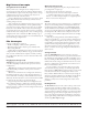
Rear Panel Description
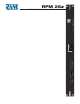
Front Panel Description
1 Signal/Overload LED meters indicate the presence of signicant audio signal or overload for Inputs and Outputs. ese 3-color
meters indicate the available headroom once the analog signal has been converted to digital: -4 dBFS (red, near clipping), -12
dBFS (yellow, high normal level), and -48 dBFS (green, low level). e analog signal level depends on the input and output set-
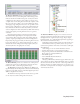
tings and is displayed in Drag Net’s Meter window.
2 AES3 LOCK LED lights solidly when a valid AES3 digital signal is detected on the AES3 input jack. ere does not need to be
an audio signal present at the input, only the “carrier” signal.
3 PRESET LED displays the number of the most recently recalled Preset, numbered 0 through 24.
4 VIP LED ashes when a change is detected on the Versatile Input Port (VIP). is port is used for direct electrical connections to
potentiometers, switches or other logic ports. See Control Connections on page Manual-4 for details.
5 ETHERNET LED ashes when an Ethernet data packet for this device is received.
6 STATUS LED reects the overall status of the unit:
Red - initializing (briey) or possible internal error.
Yellow - working, but not currently processing audio.
Green - processing audio.
7 POWER LED lights solidly when the unit is powered on.
1 POWER IEC jack connects to AC line voltage, 100-240 VAC ±10%. Use the 3-prong IEC power cable (included).
2 Balanced analog audio INPUTS 1 and 2 on Euroblock connectors.
3 Balanced analog audio OUTPUTS 1 through 6 on Euroblock connectors. Same wiring notes as the Inputs.
4 AES3 digital audio INPUT is an XLR female connector. See Digital AES3 Input on page Manual-3.
5 VERSATILE INPUT PORT provides 8 logic or voltage inputs for remote level control and Preset recall on a Euroblock
connector. See Control Connections on page Manual-4.
6 LAN and LINK reect the state of the Ethernet connection. LINK lights solidly when a valid connection to another Ethernet
device (e.g., a PC) is detected. LAN ashes when communicating with another Ethernet device.
7 10Base-T jack accepts a standard Ethernet cable with a RJ-45 connector. See Control Connections on page Manual-4.
8 DEFAULT button recalls Preset 1 when pressed. Holding this button while applying power puts the unit into a codeload mode
for updating rmware.
INPUT
AES3 OUTPUT
12
A B
1
43
2
6
5
LOCK
VIP POWER
ETHERNET
STATUS
RPM 26z
PROGRAMMABLE
MULTIPROCESSOR
PRESET
24
1 2 1 43 5 6 7
DEFAULT
100-240V
20 WATTS
50/60 Hz
MADE IN U.S.A.
RANE CORP.
10Base-T
LINK
AES3 INPUT OUTPUTS
3456
+5V
100 mA
0-5V
VERSATILE INPUT PORT
REF
1
2
3
4
5
7
6
8
GND
REF
1
2
3
4
5
7
6
8
GND
–
+
+
–
–
+
+
–
–
+
+
–
–
+
+
–
–
+
+
–
–
+
+
–
–
+
+
–
–
+
+
–
INPUTS
2 12 1
LAN
COMMERCIAL AUDIO
EQUIPMENT 24TJ
R
ACN 001 345 482
RPM 26z
1 28 4 3567