
User guide
Manual-3
Audio Connections
For each Input or Output Euroblock connector:
• Connect the (positive) audio line to the ‘+’ terminal.
• Connect the (negative) audio line to the ‘–’ terminal.
• Connect the cable shield to the ground terminal.
For those installations where the RPM 26z’s internal shield-
to-chassis connection causes interference, connect each shield
directly to the chassis PEM nut located above each Euroblock
connector, keeping the shield wrapped around the audio conduc-
tors as much as possible.
For optimum Electromagnetic Interference (EMI) immunity,
connect the shields at both ends of the cable. See the RaneNote
“Sound System Interconnection” for more information on system
connections and proper grounding practices.
Analog Input Stage
Each analog input uses a two-stage gain approach. e rst stage
contains a variable gain preamp. e second stage contains a
Digital Trim control located immediately after the A/D con-
verter.
Input Clipping
If you’ve set the Analog Gain so the input stage is not clip-
ping, it is not possible to clip the A/D converter, since there is no
additional gain between the initial input stage and the A/D con-
verter. e Digital Trim control, located after the A/D converter,
can be set to clip the signal to your heart’s content, so adjusting
this trim to provide the hottest signal to the DSPs without clip-
ping is the most important step when setting up gain structure.
For this reason, a dedicated meter displaying the signal level be-
ing passed to the DSPs is provided in each Analog Input block.
If the DSPs are working with a clipped signal, the audio is (as
expected) distorted and none too pretty, but it is not a drastic,
damaging sound. And while it’s technically possible to write a
DSP algorithm to emulate the glorious clipping distortion of
vacuum tubes, it’s not particularly useful for an installed sound
system, where the DSP power could be put to better use remov-
ing that annoying 500 Hz feedback from the podium mic. Plus,
they don’t yet make DSP chips with gold-plated substrates for
those celestial highs and that moist, supple midrange.
Analog Output Stage
Each analog output also uses a two-stage gain approach, which
diers slightly from that of the analog input stage. e rst stage
is a Digital Trim control located immediately before the D/A
converter. e second stage is an analog trim control located im-
mediately after the D/A converter. Attenuation is handled in the
analog domain, while boosting (when the incoming digital signal
is low) is handled in the digital domain. Boosting and attenuat-
ing using this two-stage approach helps maintain the RPM 26z’s
excellent noise performance.
Digital (AES3) Input
AES3 is a popular 2-channel (stereo) digital audio interface com-
monly found on professional digital audio equipment (digital
mixers, DAT machines, etc.). Each channel of the AES3 digital
stream is treated independently within the RPM 26z.
See the RaneNote “Interfacing AES3 and S/PDIF”, available
from Rane’s web site (www.rane.com/library.html), for more
information about interfacing consumer S/PDIF gear to the
professional AES3 standard.
Use the AES3 Input to:
• Connect from the AES3 Ouput of an RPM 88/44/22.
• Connect directly from the AES3 output of a digital mixer.
• Connect to an external A/D converter, eectively adding two
more analog inputs.
Incoming Sample Rate and Word Length
e AES3 input has a built-in sample rate converter capable of
accepting incoming sample rates up to 96 kHz. Sample rates ex-
ceeding the RPM 26z’s internal 48 kHz sample rate are automat-
ically downsampled. Word lengths up to 24-bits are accepted.
Control Connections
Versatile Input Port (VIP)
Eight logic input pins are provided, each capable of accepting
DC voltage between 0-5 VDC. VIP pins are used with contact
closure switches for Preset recall, or with potentiometers for
remote Level control. e functionality (Preset recall versus
control) of each pin is assignable as part of the Device Congu-
ration.
• e maximum allowable voltage on any VIP pin is 5.3 VDC.
• Use of twisted pair cable is recommended for better noise im-
munity.
• If an external device is used to generate a 0 to 5 volt signal,
connect the ground of the external device to the GND pin of
the V IP.
Preset Recall Using Contact Closure Switches
e minimum “low” voltage required to detect a contact closure
and change Presets is 2.5 V. Since the internal pull up is 100 kΩ
to +5 V, it is possible to calculate the maximum allowable cable
length, provided the wire resistance per foot (or meter) is known.
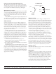
Example:
To be safe, let’s allow a maximum of 80 kΩ worth of cable
resistance. is value keeps the voltage divider formed by the
100 kΩ internal resistance and 80 kΩ cable resistance from
dropping below 2.5 V.
(5 V * 100 kΩ) / (100 kΩ + 80 kΩ) = 2.777 V
If the cable resistance is 30 Ω per 1,000 feet (305 meters)
(1,000 ft / 30 Ω) * 80,000 Ω = 2,666,666 ft (813 km)
us, you can only use 2,666,666 feet (505 miles) of twisted
pair cable before the Preset recall functionality becomes inter-
mittent (assuming the cable is properly twisted and not run
through excessive magnetic or electric elds).