
User guide

Manual-4
Remote Level Control Using Potentiometers
e VIP inherently prefers linear taper 10 kΩ potentiometers,
which provide a nice audio taper “feel” for the end user. When
used with suitable twisted pair wiring, the 10 kΩ value also of-
fers acceptable noise immunity and very long cable lengths.
AMX and Crestron Control
ere are two ways to control a Drag Net device from an AMX
or Crestron system. Use either Ethernet connectivity or use the
rear panel Versatile Input Port (VIP). Each of the 8 VIP pins
supports either switch closure Preset recall or zero-to-ve volt
control of Level.
Many AMX/Crestron applications require simple Level con-
trol and/or Preset recall. is is most easily accomplished using
the VIP (Versatile Input Port) found on all Drag Net devices.
VIP Preset Recall
Connect a switch closure or relay to a VIP pin and short it to
the ground (GND) pin to recall the corresponding Preset. For
example, shorting VIP pin 1 to the GND terminal recalls Preset
1; pin 2 recalls Preset 2, etc. ere are more details about this
functionality in the Drag Net Help le and on our Drag Net
web page. Be certain to appropriately set the VIP Allocation in
Drag Net's Parameter Window.
If GND contention of two or more pins simultaneously
occurs, the highest-numbered VIP pin takes precedence. For
example, if pin 3 is shorted to GND and pin 6 is then shorted
to GND, Preset 6 is recalled. If pin 3 is closed and then pin 2,
nothing happens -- Preset 2 is not recalled. is permits a hier-
archy of Presets when using VIP pin closures for tiered priority
paging. Since there are only eight VIP pins, you can only recall
up to eight Presets using switch closures.
ere are two ways to recall more than eight presets.
1. Use the Drag Net software Recall button which is only in-
tended for the system installer/designer.
2. Use an Ethernet command from an AMX or Crestron Ether-
net-equipped product.
[When using Drag Net's Auto Mixer/Ducker block, you have
the ability to link a VIP pin closure to a push-to-talk switch in a
paging or boardroom application. When using the Ducker block
in these applications, the VIP pins act independently provided
you Group the appropriate VIP pin with the Auto Mixer/Duck-
er's Input in Drag Net's Remote Map. Again, see our Drag Net
Applications for examples.]
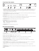
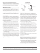
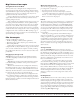
pin 1
GND
Contact
Closure
20 kΩ (linear)
Level Control
Potentiometer
VIP CONNECTION
(examples for VIP pin 1)
GND
REF
pin 1
©Rane Corporation 10802 47th Ave. W., Mukilteo WA 98275-5000 USA TEL 425-355-6000 FAX 425-347-7757 WEB www.rane.com
111216
VIP Level control
Connect a zero to ve volt DC voltage to a VIP pin from an
AMX or Crestron card to adjust any or all Level blocks placed in
the Processing Map. Use Groups in Drag Net's Remote Map to
link one or more Level blocks so they track each other when us-
ing a VIP pin. Be certain to appropriately set the VIP Allocation
in Drag Net's Parameter Window. When using VIP pins with
Level blocks, set the minimum and maximum for each Level
block by double-clicking it while it's in a Remote Map Group.
is keeps the max and min burdens within the Drag Net device
— but only when using the VIP pin to control Levels, not when
adjusting Levels from Ethernet commands.
You can use up to eight voltage control inputs linked to
Level(s) using the rear panel VIP pins. Combinations of Preset
switches & voltage Level “pots” are possible as long as combined,
they do not exceed the eight pins provided.
Since you can Group any or all Level blocks in Drag Net's
Remote Map, it's much easier to implement a stereo level control
since the Drag Net device is burdened with the task of tracking
many Levels. You can use this to your advantage when using VIP
pins to adjust multiple zones or levels. Since you can place the
Level block anywhere within the Drag Net Processing Map, you
can Group Level blocks at the input, at the output or anywhere
in-between — just place the Level block where you want it.
Ethernet control
To download the AMX or Crestron control code and documen-
tation, visit www.rane.com/dragnet
Ethernet Port
e Ethernet port is used to congure, monitor, and control the
RPM 26z via standard 10Base-T Ethernet communication. Use
an Ethernet crossover cable (one is included with each unit) to
connect the RPM 26z directly to a computer. Use a standard
(non-crossover) Ethernet cable if the RPM 26z and computer are
connected indirectly using an Ethernet repeater hub or switch.
All devices connected to the Ethernet port, including
repeater hubs, switches, and the computer’s Network Interface
Card (NIC) must support 10Base-T communication.