
User guide

Manual-5
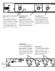
Setting the Output Level Controls
The INPUT LEVEL is an overall system sensitivity
adjustment. Use this control to decrease the overall sensitivity
of the entire sound system, including the mono subwoofer if
you are using one. You will generally want to start with this
control in the full clockwise (or 10) position.
The LOW LEVEL, HIGH LEVEL and MONO SUB
OUTPUT LEVEL controls allow you to compensate for
sensitivity variations in amplifiers and drivers. Do not use
these to adjust overall system sensitivity unless you plan to
re-align the system afterward. With these set to the 0 dB mark
and the INPUT LEVEL set to 10, the crossover yields no
level change from input to output. This is the best gain
structure and provides the best signal-to-noise performance.
Crossover Philosophy
Now it gets real fun. The idea is to set the output LEVEL
controls on the crossover so that the entire speaker system has
a uniform, flat response. Unfortunately, the room in which
the speakers are placed has a habit of always getting into the
act, so things get messy. As a result there seems to be two
schools of thought regarding the use of active crossovers.
The Set-lt-Once-And-Glue-lt School
The philosophy here is to use the crossover to flatten
system response as much as possible without room acoustics
involved. This means setting up the system outside (unless
you happen to have a very large anechoic chamber handy) and
with the aid of a realtime analyzer and pink noise source,
adjust all of the crossover outputs so that the system is as flat
as possible. Once the system is tuned, the crossover is then
locked behind a security cover (posted guard is optional) and
never again touched. It is then the job of the system
equalizer(s) to normalize or flatten the response for each
different room.
The Fix-lt-With-The-Crossover School
Here the crossover knobs get a good workout, for the
crossover is used at each location to help flatten the system
along with the equalizer.
Regardless of which school you profess, the absolute
importance and effectiveness of some kind of realtime
analyzer in your system cannot be overstressed! An analyzer
saves tremendous amounts of time and provides the absolute
consistency, accuracy, and plain old good sound that very few
ears on this earth can deliver. They are affordable, easy to use
and amazingly effective. You owe it to yourself and your
audience to at least look into one of today’s cost-effective
analyzers—you’ll wonder how you managed at all without
one.
OPERATING INSTRUCTIONS
Selecting Crossover Frequencies
Most speaker manufacturers supply low and/or high
frequency cut-off points for each driver, especially if these are
supplied in a system. These cut-off frequencies are based on
each driver’s performance, with a certain safety margin to
accommodate more gentle filter roll-offs.
The SAC 22 utilizes a 31-position precision DC control
voltage potentiometer to select the LOW/HIGH FRE-
QUENCY point. This crossover circuit design assures
consistent accuracy from Channel-to-Channel and unit-to-
unit. This is a distinct advantage over continuously variable
designs using ganged potentiometers which can yield large
variations in channel-to-channel matching. Even with 31
choices it is possible that the exact recommended Crossover
Frequency may not fall on one of the detents on the selector.
Not to panic, for drivers have their own gradual rolloffs and
tolerance variations. Just pick the closest one. When in doubt,
choose the higher Frequency setting.
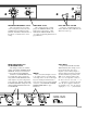
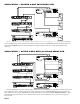
The illustration and table below details the crossover
frequencies available on the detents that are not labeled. For
best overall system results, try to choose the speaker compo-
nents so that each operates well within its recommended
limits. This provides valuable leeway so that crossover points
may be adjusted in order to fine-tune the system. This also
yields higher system reliability. If at all possible, always use
some kind of realtime analyzer to tune your crossover, and
then fine-tune each system with an equalizer. Keep reading
for further alignment details.
STEP 0 1 2 3 4 5 6 7 8 9 1011121314151617181920 21222324252627282930
SILK
SCREEN
100 125 200 250 325 500 650 1000 1500 2000 3000 3200
CALC.
FREQ.
100 100 100 107 123 141 162 187 214 246 283 325 373 429 492 566 650 746 857 985 1131 1300 1493 1715 1970 2263 2599 2986 3200 3200 3200
Figure 1. See unmarked Frequency detent steps below.
Figure 2. Frequency detent table with actual frequencies of all detent steps.