
User guide

Manual-6
©Rane Corporation 10802 47th Ave. W., Mukilteo WA 98275-5098 TEL (425)355-6000 FAX (425)347-7757 WEB http://www.rane.com
104967
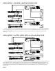
Setting the Mono Sub Output Level
Begin with the MONO SUB OUTPUT LEVEL control set
at MAX. The LOW LEVEL control has no affect on the
MONO SUB OUTPUT. Make subwoofer level changes with
either the MONO SUB OUTPUT LEVEL or with the ampli-
fier level control. If you are using the MONO SUB OUTPUT
instead of the LOW OUTPUTS, be sure the 100 Hz FILTER
is switched OUT.
Setting Levels With a Realtime Analyzer
Any good 1/3-octave realtime analyzer will do, however,
Rane makes a rather inexpensive yet accurate one—the
RA 27. We had to get our plug in.
1. Set the INPUT LEVEL as described previously on page
Manual-2, and the LOW and HIGH LEVEL controls to
minimum; leave the FREQUENCY control as it was set
previously.
2. Place the analyzer microphone at least 15 feet away from
the speaker stack, on axis (dead ahead) and about chest
level. Minimize any background noise (fans, air condition-
ers, traffic, wild animals, etc.) that could affect readings.
3. Run pink noise through the system, either through a mixer
channel or directly into the crossover. Turn all amplifier
controls at least half way up.
4. Slowly turn up the LOW LEVEL control until you hear a
healthy level of noise through the low frequency drivers (it
should sound like rumble).
4. Adjust the display controls on the analyzer so that it shows
the greatest number of 0 dB LED’s (green on Rane
equipment) below the crossover frequency.
6. Now slowly turn up the HIGH LEVEL control until the
display shows the same high frequency output level
average as the low frequency section.
IMPORTANT: Compression driver or horn high frequency
roll-off, bass roll-off, and room acoustics usually cannot be
corrected by the crossover.
If, for example, you are adjusting the HIGH FRE-
QUENCY LEVEL control and observe a decline in frequency
response somewhat above the Crossover point, then set the
HIGH LEVEL control for equal display level near the
crossover point and leave it there. Use an equalizer to correct
the roll-off problem.
If you are tuning the system in a room, the acoustics will
greatly influence the system response, as shown by the
analyzer.
Move the microphone and check the analyzer system
response at several other locations. Adjust the crossover to
reach a fixed compromise setting as necessary. If you plan to
use the analyzer only once to set the crossover, set up the
speaker system in a quiet place outside or in a very large
concert theater, and run pink noise at low levels with closer
microphone placement to keep the room acoustics out of the
picture as much as possible.
Setting Levels Using an SPL Meter and Pink Noise
Generator
First, obtain a good SPL meter from a local electronics or
hi-fi store. Second, and perhaps a little trickier, get a pink
noise generator—again try electronics stores. You may also
use a sweep or tone generator in place of a pink noise
source—be sure to look at several different tones within each
crossover section to get a good average of driver response.
1. Run pink noise into the crossover Inputs (through the mixer
or directly, as is convenient).
2. Make sure all crossover LEVEL(s) are turned all the way
down and all amplifier level controls are at least half way
up to start with.
3. Turn the crossover INPUT LEVEL all the way up. Place
the SPL meter at least 15 feet from the speaker stack and
about chest high. Once positioned, make sure that the SPL
meter remains in the exact same location for the rest of the
procedure. Minimize all background noise (fans, air
conditioners, traffic, wild animals, etc.) to get accurate
readings. Set the SPL meter to “C-weighting” and “slow” if
those switches are present.
4. Slowly turn the LOW LEVEL up until there is a healthy
rumble coming from the bass speakers. Adjust the SPL
meter and/or LOW LEVEL until you get a 0 dB reading on
the meter. After this point do not change the controls on the
SPL meter.
5. Make a note of the LOW LEVEL control setting at the 0
dB adjustment just obtained, then reduce the LOW LEVEL
to “0” so that the pink noise disappears from the bass
speakers (revel in the silence...).
6. Now slowly turn up the HIGH LEVEL control so that pink
noise is heard from the high frequency speakers. Without
changing any settings on the SPL meter, adjust the cross-
over HIGH LEVEL control until you obtain a 0 dB reading
on the SPL meter.
7. Return the LOW LEVEL to the previously recorded
setting. Now the low and high speakers are set at the same
level. The crossover should now be aligned. Make any
overall level adjustments with the INPUT LEVEL controls
and leave the output LOW and HIGH LEVEL controls
unchanged.
It is possible that you may turn one of the frequency
section output LEVEL controls all the way up and still not
have enough volume for a 0 dB reading (as determined by
previous section levels). This is probably due to different
sensitivities of amps, speakers and other level controls in the
system. When this happens, re-set the SPL meter so that it
reads 0 dB on this frequency section (you may have to “down
range” the meter and re-adjust the crossover INPUT LEVEL
control). Now go back and re-adjust the previous crossover
LEVEL controls, turning these down to get a 0 dB reading on
the meter.