
Manual

Manual-2
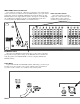
EQ BYPASS switch
When pressed to BYPASS, the filter sliders have no effect. Since actual unity
gain depends on varying slider settings, use the BYPASS switch to determine the
unity gain position of the INPUT LEVEL control by comparing ACTIVE and
BYPASS volumes.
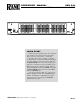
Filter level slide controls
Each of these sliders control the
output level of both channels of the 30
bandpass filters. Center position is
grounded for guaranteed flat response.
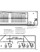
Cable Wiring
In agreement with IEC and AES/ANSI standards, XLR wiring convention is pin
2 Positive (hot), pin 3 Negative (cold), and pin 1 Signal ground (for unbalanced
use). Pin 1 and the connector case or shell are tied to chassis ground.
INPUT LEVEL control and indicators
This controls the overall level. 0 dB gain is reached at the center detent with all
sliders centered at their 0 dB detents. Set the INPUT LEVEL to give equal volumes
with the EQ switched to ACTIVE or BYPASS, after setting the sliders (see EQ
BYPASS switch below). Apply sufficient signal to the input to occasionally light
the +4 dBu indicator. Flashing of the OL (overload) LED during peaks can be
avoided by turning the INPUT LEVEL or boosted Filters down.