
Operator`s manual

Manual-9
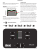
Basic Effects Controls
e selected effect is edited with the remaining soft controls. e
function of some controls depends on the selected Effect. Spe-
cific control funtions are outlined in the operational details for
each Effect (see page Manual-10). e basic operation of these
controls is outlined here:
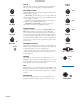
PGM 1 CUE
PGM 2 CUE
MAIN MIX CUE
CUE
PGM 1 EFFECT CUE
PGM 2 EFFECT CUE
MAIN MIX EFFECT CUE
AUX BUS EFFECT CUE
MASTER CUE
CUE PAN
ON
OFF
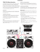
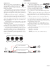
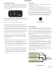
Eects Cue Block Diagram
B5 B6
J2
ON ON
CUE EFFECT
TRANSFORM
B5 Toggles the Effects Cue On / Off. is is a global setting and
does not change state when toggling between Effects Processors.
See the Effects Cueing section for details.
B6 toggles the selected Effects Processor On / Off.
J1 and J2 joy-switches may operate as transform switches or to
control effects parameters. J1 and J2 each feature an eight-posi-
tion joy switch, a push switch and a green mode indicator. If the
green mode indicator is off, the associated joystick operates as a
transform switch. If the green mode indicator is lit, the joystick
is assigned to an effect parameter as outlined below. Pressing the
joystick toggles between the two modes of operation. If a second
function is not available, pressing the joystick has no effect.
P1 and P2 encoders may be used to control Effect parameters.
P1 and P2 each feature a rotary encoder, a push switch and a
green mode indicator. ere are two basic modes of operation for
each of these controls:
1) e first mode of operation allows the encoder to present two
controls, with the push switch toggling between the two.
• Green mode indicator is off, the encoder adjusts parameter #1.
• Green mode indicator is on, the encoder adjusts parameter #2.
If the second parameter is not used, pushing the control does
nothing and the green mode indicator remains off.
2) e second mode of operation allows the encoder to operate
as a single rotary encoder with a Tap function. In this mode
of operation the green mode indicator is normally off and
lights only while the push switch is pressed, indicating a Tap
is being read. ere is no second rotary encoder function in
this mode.
Effects Cueing
Inserting an Effects Processor in one of the four possible insert
points automatically sends and returns audio to the appropriate
insert point, and connects the Effects Processor Cue signal to the
proper location. e Effect Cue switch is global, meaning that if
it’s on it stays on when switching between Effects Processor 1 and
Effects Processor 2. e Effect Cue is only active for the selected
Effects Processor.
To Cue an Effect before it is heard in the Main Mix, leave
the Effect off and engage the Effect Cue (B5). For an Effect Cue
to be heard in the headphones, the Effect Processor must be se-
lected, Effect Cue must be on and the Cue Pan and Master Cue
controls must be in the correct position.
e Effects Cue for an Effect inserted in PGM 1 or PGM 2
is sent to the appropriate side of the Cue Pan control, and like a
normal PGM 1 or PGM 2 Cue, is only heard if the Master Cue
switch is off. Panning between PGM 1 and PGM 2 Cue works
the same for both Effects Cue and normal Cue.
e Effects Cue for an Effect inserted in Master or Aux Bus
is only heard in the headphones if the Master Cue switch is on.
is scheme leaves Cue Pan and Master Cue features intact, even
when Cueing effects.
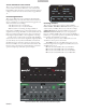
FOOT SWITCH
Footswitch
e last soft control is the optional footswitch. A footswitch al-
lows hands-free control of:
• Looping: in point, out point, and loop.
• Recording: start /stop record and load to either Virtual Deck.
ree buttons gives the most flexibility, but you can use
setup in the Scratch LIVE effects control panel for one- or two-
button footswitches (see page Manual-33). e foot switch needs
to be a passive pull-down device capable of grounding the TIP,
RING or TIP and RING to get the three possible states. Good
choices are the DigiTech FS300 or GNXFC. A schematic of a
3-switch foot switch is in the Appendix on page Manual-40: