Professional + 90 Induction User Guide & Installation & Service Instructions U109941 - 02
Contents 1. Before You Start... 1 2. Cooker Overview 3 3. Cooking Tips 11 4. Fan Oven Cooking Table 12 5. Cleaning Your Cooker 13 6. Troubleshooting 16 7. Installation 18 8. Servicing 22 9. Circuit Diagrams 27 10.
1. Safety Personal Safety Thank you for buying a Rangemaster cooker. It should give you many years of trouble-free cooking if installed and operated correctly. It is important that you read this section before you start, particularly if you have not used an induction cooker before. Important information for pacemaker and implanted insulin pump users: The functions of this hob comply with the applicable European standards on electromagnetic interference.
Use dry oven gloves when applicable – using damp gloves might result in steam burns when you touch a hot surface. Do not use a towel or other bulky cloth in place of a glove – it might catch fire if brought into contact with a hot surface. NEVER allow anyone to climb or stand on the hob. Do not stand or rest heavy objects on the hob. Although the ceramic surface is very strong, a sharp blow or sharp falling object (e.g. a salt cellar) might cause the surface to crack or break.
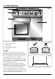
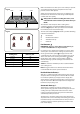
2. Cooker Overview ArtNo.025-0005 - Overview - 90 induction - 2 button clock & GO grill � Fig.2-1 � � � � The 90 induction cooker (Fig.2-1) has the following features: A. B. C. D. E. Fig.2-2 5 induction cooking zones A control panel A glide-out grill Main programmable fan oven Tall fan oven ArtNo.312-0004 Correct pans ceramic The Hob Use only pans that are suitable for induction hobs. We recommend stainless steel, enamelled steel pans or cast iron pans with enamelled bases.
Make sure that the base of the pan is clean and dry to prevent any residue burning onto the hob panel. This also helps prevent scratches and deposits. Fig.2-4 ����� ����� ����� Always use pans that are the same size as (or slightly larger than) the areas marked on the hob. Using a lid will help the contents boil more quickly. ArtNo.313-0002 - 110 induction hob rating ����� Always take care before touching the surface, even when the hob is turned off.
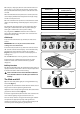
Once the [A ] is displayed, turn the control knob to the level of your choice (1 to 9). The pan will heat up at 100% power for a specified time before the power is reduced to the level selected. ���������������������� ����������������� ����������� When the Automatic Heat-up function is activated, the hob control display will flash alternately between the [A] setting and the chosen power level.
Once the grill has preheated, slide the carriage out again. With the trivet back in place with the food on it, slide the carriage back into the grill chamber. Ensure that it is pushed right in. Fig.2-9 ArtNo.331-0002 Grill pan high/low position Accessible parts may be hot when the grill is in use. Young children should be kept away. The grill pan grid can be turned over to give two grilling positions (Fig.2-9).
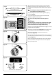
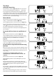
The Clock Setting the time of day ArtNo.300-0005 2BC minute minder setting Fig.2-14 ArtNo.300-0006 2BC minute minder setting 2 Fig.2-15 ArtNo.301-0007 2BC Stopping the oven 1 Fig.2-16 ArtNo.301-0008 2BC Stopping the oven 2 Fig.2-17 ArtNo.301-0009 2BC Setting the cooking timer Fig.2-18 ArtNo.301-0010 2BC Setting the cooking time Fig.2-19 ArtNo.301-0008 2BC Stopping the oven 2 Fig.2-20 The LCD clock is shown in (Fig.2-13). When the clock is first connected, the display flashes ( 0.
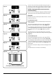
If you are out, do not worry about the beeper going off – it will stop on its own after a while. When you return, turn the Timer knob to the vertical () to return to manual cooking. Art No. 301-0011 2BC Activating the key lock 1 Fig.2-21 AUTO is showing, but you want to revert to manual cooking You can cancel any automatic settings by briefly turning the Timer knob to the clock symbol () and then releasing it. ArtNo.301-0012 2BC Activating the key lock 2 Fig.
Accessories Fig.2-27 Oven Shelves – Left-hand (Main) Oven � In addition to the flat shelves (Fig.2-26), some models are supplied with a drop shelf (Fig.2-27). The drop shelf increases the possibilities for oven shelf spacing. ArtNo.320-0010 Flat & drop shelves The oven shelves can be easily removed and refitted. � Pull the shelf forward until the back of the shelf is stopped by the shelf stop bumps in the oven sides (Fig.2-28).
Main Oven Light Fig.2-36 Press the button to turn the light on (Fig.2-36). If the oven light fails, turn off the power supply before changing the bulb. See the ‘Troubleshooting’ section for details on how to change the bulb. ArtNo.
DocNo.030-0002 - Cooking tips - electric 3. Cooking Tips Tips on Cooking with the Timer General Oven Tips If you want to cook more than one dish, choose dishes that require approximately the same cooking time. However, dishes can be ‘slowed down’ slightly by using small containers and covering them with aluminium foil, or ‘speeded up’ slightly by cooking smaller quantities or placing them in larger containers. The wire shelves should always be pushed firmly to the back of the oven.
4. Fan Oven Cooking Table The oven control settings and cooking times given in the table below are intended to be used AS A GUIDE ONLY. Individual tastes may require the temperature to be altered to provide a preferred result. Food is cooked at lower temperature in a fan oven than in a conventional oven. When using recipes, reduce the fan oven temperature by 10°C and the cooking time by 5-10 minutes. The temperature in the fanned oven does not vary with height in the oven so you can use any shelf.
ArtNo.045-0004 - Cleaning - 90 induction - tpl glzd dr & GO grill 5. Cleaning Your Cooker Isolate the electricity supply before carrying out any major cleaning. Allow the cooker to cool. Fig.5-1 Never use paint solvents, washing soda, caustic cleaners, biological powders, bleach, chlorine based bleach cleaners, coarse abrasives or salt. Do not mix different cleaning products – they may react together with hazardous results.
Once you have removed as much as possible with the scraper, follow the ‘Daily Care’ procedure outlined above. Fig.5-2 Glide-out Grill The grill pan and grid should be washed in hot soapy water. After grilling meats or any foods that soil, leave to soak for a few minutes immediately after use. Stubborn particles may be removed from the grid using a nylon brush. Alternatively, the grill pan can be washed in a dishwasher. ArtNo.331-0001Grill pan pulled forwards ArtNo.
Door Panel Fig.5-7 Open the oven door slightly and remove the front panel fixing screws from the door sides, two each side (Fig.5-7). Carefully lift off the outer door panel. The inside face of the glass panels can now be cleaned – take care not to disturb or wet the door insulation. The door is triple glazed but the inner two panels are fixed and should not be separated. After cleaning, carefully refit the outer door panel and replace the side fixing screws. ArtNo.
6. Troubleshooting Steam is coming from the oven When cooking foods with a high water content (e.g. oven fries) there may be some steam visible at the rear grille. Take care when opening the oven door, as there may be a momentary puff of steam when the oven door is opened. Stand well back and allow any steam to disperse. Interference with and repairs to the hob by unqualified persons are not allowed. Do not try and repair the hob as this may result in injury and damage the hob.
The oven is not cooking evenly If you are cooking a large item, be prepared to turn it round during cooking. If two racks are used, check that space has been left for the heat to circulate. When a baking sheet is put into the oven, make sure it is placed centrally on the rack. Check that the door seal is not damaged. A dish of water when placed on the rack should be the same depth all over. (For example, if it is deeper at the back, then the back of the range should be raised up or the front lowered).
ArtNo.065-0004 - Installation - 90 induction 7. Installation Dear Installer You will also need the following tools: Before you start your installation, please complete the details below, so that, if your customer has a problem relating to your installation, they will be able to contact you easily. 1. 2. 3. ���������������� 4. 5. 6. 7. 8. 9. ������������������� ArtNo.
Positioning the Cooker ArtNo.090-0009 - 90 2BC cooker min spacings Fig.7-1 Fig.7-1 shows the minimum recommended distance from the cooker to nearby surfaces. ���� ��� The cooker should not be placed on a base. ����� ��� ���� ��� The hotplate surround should be level with, or above, any adjacent work surface. A gap of 75mm should be left between each side of the cooker ABOVE the hotplate level and any adjacent vertical surface.
Lower the Two Rear Rollers Fig.7-5 First fit the levelling tool on the hexagonal adjusting nut (Fig.7-5). ArtNo.010-0002 Rear roller nut Make 10 complete (360º) turns clockwise (Fig.7-6). (This means turning and removing the levelling tool 20 times.) Make sure you lower BOTH REAR ROLLERS. There are two adjusting nuts, one for each roller, at both the front bottom corners of the cooker. Completing the Move Unfold the rear edge of the pack base tray.
Electrical Connection Fig.7-9 The cooker must be installed by a qualified electrician, in accordance with all relevant British Standards/Codes of Practice (in particular BS 7671), or with the relevant national and local regulations. � � WARNING: THE APPLIANCE MUST BE EARTHED.
WARNING – SERVICING TO BE CARRIED OUT ONLY BY AN AUTHORISED PERSON Disconnect from electricity before servicing. Check appliance is safe when you have finished. 8. Servicing ArtNo.081-0003 - Service - 90 induction Fig.8-1 Disconnect the cooker from the electricity supply before servicing, particularly before removing any of the following: control panel, side panels, ceramic hob, or any of the electrical components or cover boxes. Before reconnection, check that the appliance is electrically safe.
WARNING – SERVICING TO BE CARRIED OUT ONLY BY AN AUTHORISED PERSON Disconnect from electricity before servicing. Check appliance is safe when you have finished. 5. To Replace the Light Switch Disconnect from electricity supply. Remove the control panel (see 1). Note: The old switch may be destroyed during removal. Remove the old switch from its bezel by gripping the switch body behind the control panel and twisting sharply. Remove the switch bezel by folding back its locking wings and pushing forward.
WARNING – SERVICING TO BE CARRIED OUT ONLY BY AN AUTHORISED PERSON Disconnect from electricity before servicing. Check appliance is safe when you have finished. Fig.8-3 9. Fig.8-4 Open the oven door. Support the door and remove the two screws securing the upper hinge and gasket to the cooker front (Fig.8-3). Remove the door from the lower hinge by lifting slightly and moving outwards (Fig.8-4). � � ArtNo.320-0001 Door hinges To Replace an Oven Door The door is heavy, so take care.
WARNING – SERVICING TO BE CARRIED OUT ONLY BY AN AUTHORISED PERSON Disconnect from electricity before servicing. Check appliance is safe when you have finished. 16. To Replace an Oven Door Seal ArtNo.320-0004 Oven door keep Open the oven door. The seal has small hooks that hold it in place by locating into holes in the rear door face on the main oven and oven front face on tall oven. At the corner, pull the seal diagonally away from the door centre until the hook is released (Fig.8-10).
WARNING – SERVICING TO BE CARRIED OUT ONLY BY AN AUTHORISED PERSON Disconnect from electricity before servicing. Check appliance is safe when you have finished. Fig.8-13 21. To Replace an Oven Fan Fig.8-14 Disconnect from electricity supply. Pull the cooker forward to gain access to the rear. Remove the screws securing the electric cover to the back sheet and remove the cover. ArtNo.324-0007 Unscrewing the bulb cover Disconnect the three terminals connected to the fan noting their position.
9. Circuit Diagram: Oven ArtNo.095-0003 - Circuit diagram - 90 induction � ArtNo.
Circuit Diagram: Hob � � �� ����� �� � ����� �� �� ����� � �� �� �� � �� � �� �� ����� � � �� �� ��� � � �� ����� � � � �� �� �� ��� � �� � � ��� � � � � �� 8 8 8 8 8 �� � � �� � � � �� � ArtNo.
10. Technical Data ArtNo.105-0003 - Technical data - 90 induction INSTALLER: Please leave these instructions with the User. DATA BADGE LOCATION : Cooker back, serial number repeater badge below oven door opening. Connections Electric 220 - 240V 50Hz Dimensions Overall height minimum 902mm maximum 927mm Overall width 900mm Overall depth 650mm Refer to 'Positioning the Cooker'. Ratings ����� ����� ����� ArtNo.
DocNo.000-0001 - Back cover Rangemaster ���������������������������������������� ArtNo.000-0003 CE logo www.rangemaster.co.