Britain’s No.
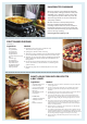
RANGEMASTER COOKWARE Our range cookers are well known for providing the best possible cooking performance and years of faithful service. However, a great cooker alone cannot guarantee perfect results every time. The other vital ingredients are of course enthusiasm and quality cookware. We offer cookware to work perfectly with all fuel types manufactured by Rangemaster, including induction hobs.
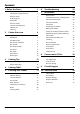
Contents 1. Before You Start... 1 6. Troubleshooting 22 Important! 1 Installation and Maintenance 1 7. Installation 24 Peculiar smells 1 Dear Installer 24 If you smell gas 1 Safety Requirements and Regulations 24 Ventilation 1 Provision of Ventilation 24 Personal Safety 1 Location of Cooker 25 Ceramic Warming Zone 2 Conversion 25 Cooker Care 3 Positioning the Cooker 26 Cleaning 3 Moving the Cooker 26 Fitting the Stability Bracket or Chain 27 27 2. 3.
iv
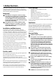
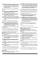
1. Before You Start... If you smell gas Your cooker should give you many years of trouble-free cooking if installed and operated correctly. It is important that you read this section before you start, particularly if you have not used a dual fuel cooker before. • DO NOT turn electric switches on or off.
NEVER leave a chip pan unattended. Always heat fat nn slowly, and watch as it heats. Deep fry pans should Accessible parts will become hot during use and will nn retain heat even after you have stopped cooking. Keep babies and children away from the cooker and never wear loose-fitting or hanging clothes when using the appliance. Always be certain that the controls are in the OFF position when the oven is not in use, and before attempting to clean the cooker. be only one third full of fat.
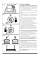
DO NOT place anything between the base of the pan nn and the warming zone surface (e.g. asbestos mats, Fig. 1.1 aluminium foil, wok cradle). Take care NOT to place metallic objects such as nn knives, forks, spoons and lids on the hob surface since they can get hot. The appliance is not intended to be operated by nn means of external timer or separated remote-control ArtNo.324-0001 Steam burst system. Avoid warming an empty pan. Doing so may damage nn both the warming zone and pan. Fig. 1.
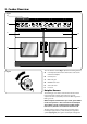
2. Cooker Overview DocNo.020-0006 - Overview - 100DF - Prof+ Fig. 2.1 A B C E D F The 110 dual fuel cooker (Fig. 2.1) has the following features: Fig. 2.2 A. Four hotplate burners with a wok burner and ceramic multi-zone hotplate B. Control panel C. Glide-out grill D. Multifunction oven E. Slow cook oven F. Fan oven Hotplate Burners The drawing by each of the control knobs indicates which burner that knob controls.
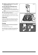
gas. Keep holding the knob pressed in to let the gas through to the burner for about ten seconds. Fig. 2.3 If, when you let go of the control knob, the burner goes out, then the FSD has not been bypassed. Turn the control knob to the OFF position and wait for one minute before you try again, this time making sure to hold in the control knob for slightly longer. Adjust the flame height to suit by turning the knob counterclockwise (Fig. 2.3).
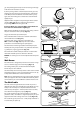
The Ceramic Hotplate Fig. 2.11 The hotplate area on the left-hand side is dual purpose. It can be used either as a ceramic hob to heat a pan in the usual way (Fig. 2.11) or it can be used to heat the supplied griddle. The rear area, marked with a ring is for cooking with a pan. There are two elements that allow either the whole of the area to be heated or just the rear half. To heat the whole area, turn the control knob clockwise (Fig. 2.12).
The Griddle Fig. 2.16 The griddle (Fig. 2.17) is designed to fit securely on the locating pins over the ceramic heating area (Fig. 2.18). Do not try to use it over one of the gas burners. It will not be securely held and you may damage the non-stick finish. There are two elements that allow either the whole of the area to be heated or just the rear half. ArtNo.312-0006 Correct pan sizes To heat the whole area, turn the knob clockwise (Fig. 2.19).
The Glide-out Grill Fig. 2.21 Open the door and pull the grill pan carriage forward using the handle (Fig. 2.21). The grill has two elements that allow either the whole area of the pan to be heated or just the right-hand half. To heat the whole grill, turn the knob clockwise (Fig. 2.22). To heat the right-hand half, turn the knob counter-clockwise. The neon indicator light by the grill control will come on. ArtNo.
food cooking until you have become accustomed to this function. Conventional Oven (Top and Base Heat) This function combines the heat from the top and base elements. It is particularly suitable for roasting and baking pastry, cakes and biscuits. Multifunction Oven Functions Rapid Response The Rapid Response setting enables you to preheat the oven faster than normal. It uses the fan oven element with additional heat from one of the elements in the top of the oven.
The Slow Cook Oven Fig. 2.24 The Slow Cook oven is intended for slow cooking items such as casseroles, joints of meat, etc. Your Slow Cook oven is capable of cooking a complete meal; for instance – casserole, rice pudding and jacket potatoes – or just warming the dishes (use only heat resistant dishes). Points to remember when Slow Cooking: • Preheat the oven for 20–30 minutes before starting to cook. • Do not allow dishes to touch the heating elements either side of the oven.
Slow Cook Oven The graduated temperature scale on the fascia (Fig. 2.27) allows you to either cook slowly for several hours (A) or all day whilst you are out (B). ArtNo.300-0005 2BC Fig. 2.28 minute minder setting For long scale cooking select the thicker end of the scale and for a shorter cooking time select the thinner end of it. C The Clock A You can use the clock to turn the left-hand oven on and off. The clock must be set to the time of day before the oven will work.
To Stop the Multifunction Oven at a Specific Time of Day ArtNo.301-0008 2BC Stopping the oven 2 Fig. 2.33 You have set the required temperature and function mode for the Multifunction Oven and you would like the Multifunction Oven to automatically stop. G A TOP TIP B Make a note of the current time so you do not forget. ArtNo.301-0008 2BC Stopping the oven 2 Fig. 2.34 1. Turn the Timer (A) knob to the Stop Time (G) setting (Fig. 2.33). 2.
To Start and Stop the Multifunction Oven ArtNo.301-0010 2BC Setting the cooking time The Multifunction Oven allows you to automatically start and stop by a combination of the length of the cooking time and the stop time. Giving you the flexibilty to cook casseroles etc while you are out. You cannot set the actual start time. Fig. 2.36 F 1. Turn the Timer (A) knob to the Cook Time (F) setting. Turn the Adjusting (B) knob clockwise to set the length of the cooking time required e.g. 50 seconds (Fig. 2.
Accessories Fig. 2.43 Oven Shelves Shelf guard The oven shelves (Fig. 2.43) are retained when pulled forward but can be easily removed and refitted. Pull the shelf forward until the back of the shelf is stopped by the shelf stop bumps in the oven sides (Fig. 2.44). Lift up the front of the shelf so the back of the shelf will pass under the shelf stop and then pull the shelf forward (Fig. 2.45).
3. Cooking Tips Tips on Cooking with the Timer General Oven Tips If you want to cook more than one dish, choose dishes that require approximately the same cooking time. However, dishes can be ‘slowed down’ slightly by using small containers and covering them with aluminium foil, or ‘speeded up’ slightly by cooking smaller quantities or placing them in larger containers. The wire shelves should always be pushed firmly to the back of the oven.
4. Cooking Table DocNo.031-0004 - Cooking table - electric & fan single cavity The oven control settings and cooking times given in the table below are intended to be used AS A GUIDE ONLY. Individual tastes may require the temperature to be altered to provide a preferred result. Food is cooked at lower temperature in a fan oven than in a conventional oven. When using recipes, reduce the fan oven temperature by 10 °C and the cooking time by 5-10 minutes.
5. Cleaning Your Cooker Fig.5.1 Essential Information A Isolate the electricity supply before carrying out any thorough cleaning. Allow the cooker to cool. C Never use paint solvents, washing soda, caustic nn cleaners, biological powders, bleach, chlorine based B bleach cleaners, coarse abrasives or salt. Do not mix different cleaning products – they may nn react together with hazardous results.
Ceramic Hotplate Fig.5.5 Daily Care First of all, make sure that the heat indicator light is off and that the cooking surface is cool. Apply a small dab of ceramic cleaning cream in the centre of the area to be cleaned. Dampen a clean paper towel and work the cream onto the cooking surface. As a final step, wipe the cooking surface with a clean, dry paper towel.
Glide-out Grill Fig.5.6 The grill pan and trivet should be washed in hot soapy water. Alternatively, the grill pan can be washed in a dishwasher. After grilling meats or any foods that soil, leave to soak for a few minutes immediately after use. Stubborn particles may be removed from the trivet using a nylon brush. Before you remove any of the grill parts for cleaning, nn make sure that they are cool, or use oven gloves. DO NOT use any abrasive substances. nn ArtNo.331-0001Grill pan pulled forwards Fig.
Control Panel and Doors Fig.5.11 Avoid using any abrasive cleaners, including cream cleaners. For best results, use a liquid detergent. The same cleaner can also be used on the doors. Alternatively, use a soft cloth wrung out in clean hot soapy water. You can use the same method for cleaning the control panel and knobs. After cleaning, polish with a dry cloth. Glass Fronted Door Panels The oven door front panels can be taken off so that the glass panels can be cleaned.
Cleaning Table Cleaners listed (Table 5.1) are available from supermarkets or electrical retailers as stated. For enamelled surfaces use a cleaner that is approved for use on vitreous enamel. Regular cleaning is recommended. For easier cleaning, wipe up any spillages immediately. Hotplate Part Finish Recommended Cleaning Method Hob top (including burner heads and caps) Enamel, stainless steel, aluminium Hot soapy water, soft cloth. Any stubborn stains remove gently with a nylon scourer.
6. Troubleshooting An oven fan is noisy The note of the oven fan may change as the oven heats up – this is perfectly normal. Hotplate ignition or hotplate burners faulty Is the power on? Is the clock illuminated? If not, there maybe something wrong with the power supply. The knobs get hot when I use the oven or the grill. Can I avoid this? Yes, this is caused by heat rising from the oven or the grill, and heating them up. Do not leave the oven door open.
Oven not coming on Is the power on? Is the clock illuminated? If not, there may be something wrong with the power supply. Fig.6.1 Is the cooker supply on at the isolator switch? ArtNo.324-0005 Oven light bulb Has the time of day been set? Is the key symbol [] showing in the display to signify that the oven is locked? See the ‘Clock’ section of the instructions for more information on the key lock feature. Fig.6.
INSTALLATION Check the appliance is electrically safe and gas sound when you have finished. 7. Installation Dear Installer In the UK the cooker must be installed in accordance with: Before you start your installation, please complete the details below, so that, if your customer has a problem relating to your installation, they will be able to contact you easily. • • • Installer’s Name Installer’s Company • • ArtNo.
INSTALLATION Check the appliance is electrically safe and gas sound when you have finished. Checking the parts: Location of Cooker The cooker may be installed in a kitchen/kitchen diner but NOT in a room containing a bath or shower. 3 pan supports This appliance is designed for domestic cooking only. Use for any other purpose could invalidate any warranty or liability claim. Note: An appliance for use on LPG must not be installed in a room or internal space below ground level, e.g. in a basement.
INSTALLATION Check the appliance is electrically safe and gas sound when you have finished. Positioning the Cooker Fig.7.1 Fig.7.1 and Fig.7.2 show the minimum recommended distance from the cooker to nearby surfaces. 75mm min 650mm min The cooker should not be placed on a base. The hotplate surround should be level with, or above, any adjacent work surface. A gap of 75 mm should be left between each side of the cooker ABOVE the hotplate level and any adjacent vertical surface.
INSTALLATION Check the appliance is electrically safe and gas sound when you have finished. Lowering the Two Rear Rollers Fig.7.5 To adjust the height of the rear of the cooker, first fit a 13 mm spanner or socket wrench onto the hexagonal adjusting nut (Fig.7.5). Rotate the nut – clockwise to raise – counterclockwise to lower. Make 10 complete (360°) turns clockwise. Make sure you lower BOTH REAR ROLLERS. Completing the Move Unfold the rear edge of the cardboard base tray.
INSTALLATION Check the appliance is electrically safe and gas sound when you have finished. Conversion to Another Gas Fig.7.10 If the appliance is to be converted to another gas do the conversion at this point. See the conversion section of these instructions. Gas inlet Levelling 600 300 250 You are recommended to use a spirit level on a shelf in one of the ovens to check for level.
INSTALLATION Check the appliance is electrically safe and gas sound when you have finished. Pressure Testing Current Operated Earth Leakage Breakers The gas pressure can be measured at one of the hotplate burner injectors (not a wok burner). The combined use of your induction cooker and other domestic appliances may cause nuisance tripping, so we recommend that the cooker is protected on an individual RCD (Residual Current Device) or RCBO (Residual Current Breaker with Overload).
WARNING – SERVICING TO BE CARRIED OUT ONLY BY AN AUTHORISED PERSON Disconnect from electricity and gas before servicing. Check appliance is safe when you have finished. 8. Conversion to LP Gas Check the ‘Technical Data’ section at the back of the book that the hob is convertible to the gas you want to use. A suitably competent person must perform the conversion. After conversion the installation must comply with the relevant regulations and also the local electricity supply company requirements.
WARNING – SERVICING TO BE CARRIED OUT ONLY BY AN AUTHORISED PERSON Disconnect from electricity and gas before servicing. Check appliance is safe when you have finished. Pressure Testing Connect the appliance to the gas supply. The gas pressure can be measured at one of the hotplate injectors (not a wok burner). Lift off a burner head. Fit the pressure gauge to the jet. Turn on and light one of the other burners. Turn on and press in the control knob for the burner with the pressure gauge fitted.
9. Circuit Diagram K b r y bk br br A1 b v br r br r K K b b J bk A2 1.
10. Technical Data THE COOKER IS CATEGORY: CatII2H3+. It is supplied set for group H natural gas. A conversion kit from NG to LP is available for the cooker. INSTALLER: Please leave these instructions with the user. DATA BADGE LOCATION: Cooker back, serial number repeater badge below oven door opening. COUNTRY OF DESTINATION: GB, IE, FR, NL, DE, SE, IT, AT, CH, LU, BE.
Hotplate Efficiency Brand Falcon Model Identification Excel Size 110 Type Dual Fuel Type of Hob Gas Number of gas burners 5 Auxiliary / Small Burner (EE gas burner) - Semi Rapide / Medium Burner (EE gas burner) 58% Semi Rapide / Medium Burner (EE gas burner) 58% Rapide / Large Burner (EE gas burner) 56% Rapide / Large Burner (EE gas burner) - Wok (EE gas burner) 53% Wok (EE gas burner) - Hotplate EE gas hob (*) - Type of Hob Radiant Number of electric zones 2 Zone 1 - Ø cm 1
Oven Data Brand Rangemaster Model identification Excel Type of oven Electric Mass kg 130 Number of cavities 2 Left-hand Efficiency Fuel type Electric Cavity type Multifunction Power - conventional 2.2 Power - forced air convection 2.5 Volume Litres 73 Energy consumption (electricity) - conventional kWh / cycle 1.08 Energy consumption (electricity) - forced air convection kWh / cycle 0.91 Energy efficiency index - conventional 126.
Notes 36
Notes 37
Notes 38
hobs must be reported within 14 days. Scratches caused by usage are not covered. Accidental damage is not covered by the manufacturer’s warranty. Name of Appliance & Colour* For warranty compliance, the requirements for the appliance are: • Has been correctly installed in accordance with current legislation, relevant British and European Standards and Codes of Practice, by a suitably competent person registered with Gas Safe or equivalent body and where applicable a qualified electrician.
ALSO PART OF THE RANGEMASTER COLLECTION... Refrigeration Built-in Cooking Dishwashing Sinks & Taps Clarence Street Royal Leamington Spa Warwickshire CV31 2AD England Tel: +44 (0) 1926 457400 Fax: +44 (0)1926 450526 E-mail: consumers@rangemaster.co.uk Consumer Services Tel: +44 (0) 800 804 6261 www.rangemaster.co.uk Britain’s No.1 Range Cooker For ROI Enquiries Tel: 1850 302 502 Search Rangemaster UK Registered in England and Wales. Registration No.