OPLHD60 – OPLHD90 – OPLHD100 – OPAL HOOD Instructions Manual www.rangemaster.co.
INDEX EN RECOMMENDATIONS AND SUGGESTIONS ..................................................................................................................... 3 CHARACTERISTICS ............................................................................................................................................................. 4 INSTALLATION.................................................................................................................................................................
RECOMMENDATIONS AND SUGGESTIONS The Instructions for Use apply to several versions of this appliance. Accordingly, you may find descriptions of individual features that do not apply to your specific appliance. INSTALLATION • The manufacturer will not be held liable for any damages resulting from incorrect or improper installation.
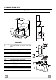
CHARACTERISTICS Dimensions 0 300 330 380 Min. 330 - Max. 640 20 Components Ref. 1 Q.ty Product Components 1 Hood Body, complete with: Controls, Light, Blower, Filters 2.1 1 Upper Section 2.2 1 Lower Section 8 1 Directional Air Outlet grille 9 1 Reducer Flange ø 150 – 120 mm 10 1 Adapting ring ø 120-125 mm 15 1 Angle iron 16 1 Filter cover Ref. Q.ty Installation Components 7.2.
INSTALLATION Wall drilling and bracket fixing 1÷2 540 2 140 140 1 2 788 11 164 164 450 1 11a 12a X 7.2.1 As a first step, proceed with the following drawings: • a vertical line up to the ceiling or up to the upper limit, at the centre of the area in which the hood is to be fitted; • a horizontal line at a minimum 788 mm above the cooker top. • Mark a point (1) on the horizontal line, 164 mm to the right of the vertical reference line.
Fitting the hood body • Open the doors/the door (See section Open Panels). • Remove the Metal grease filters using the handles provided. • Adjust the two screws Vr, in the brackets 11a, so that they are at the start of their travel. • Hook the hood body to the two brackets 11a. • From the inside of the hood body, turn screws Vr to level the hood body itself. • Fasten the safety screw 12a. • Close the doors/the door again.
Recirculation Version Air Outlet To install the Recirculation Version of the hood, the Activated charcoal filter must be fitted, see paragraph “ Activated charcoal filter (Recirculation version)”. 8 12d 12c 16 • Screw the filter cover onto the air outlet, using four screws 12c (2.9 x 12.5). • Fix the directional grille 8 on the recirculation air outlet using the 2 screws 12d (2,9 x 9,5) provided.
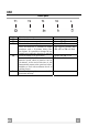
USE Control panel T1 Button T1 T2 T3 T4 L EN T2 T3 Function Turns the Motor off. Turns the motor on at speed one Turns the Motor on at speed two Press and hold for 2 seconds to enable shutdown with a 20 minute delay (Motor+Lights). It is possible to change the operating speed when this function is enabled. Turns the Motor on at speed three Press and hold for 2 seconds to activate Intensive speed, which is timed to run for 10 minutes.
MAINTENANCE Opening Panel • • • • Open the Panel by pulling it. The panel can be locked in any position. Clean the outside with a damp cloth and neutral detergent. Clean the inside using a damp cloth and neutral detergent; do not use wet cloths or sponges, or jets of water; do not use abrasive substances.
Activated charcoal filter (Recirculation version) A These filters are not washable and cannot be regenerated, and must be replaced approximately every 4 months of operation, or more frequently with heavy usage. • • • • • • REPLACING THE ACTIVATED CHARCOAL FILTER Open the comfort panels pulling them downwards. Remove the metal grease filters Remove the saturated activated charcoal filter as shown (A). Fit the new filters (B). Replace the metal grease filters. Close the comfort panels.
AGA RANGEMASTER GROUP PLC 991.0301.