
User guide

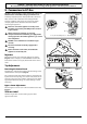

WARNING – SERVICING TO BE CARRIED OUT ONLY BY AN AUTHORISED PERSON
Disconnect from electricity and gas before servicing. Check appliance is safe when you have nished.
27
A
B
C
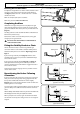
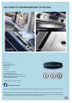
ArtNo.311-0010 Injectors
Fig.8-1
A – Jet, B – Internal injector, C – External injector
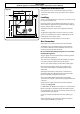
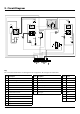
ArtNo.270-0032 - 90 Prof+ FX - Removing the control panel
Professional + 100 FX
Fig.8-2
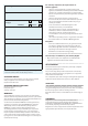
Check the ‘Technical Data’ section at the back of the book
that the hob is convertible to the gas you want to use.
A suitably competent person must perform the conversion.
After conversion the installation must comply with the
relevant regulations and also the local electricity supply
company requirements. Read the instructions before
converting this appliance.
Failure to convert the appliance correctly could
invalidate any warranty or liability claims and lead
to prosecution.
When servicing or replacing gas-carrying
components disconnect from the gas supply before
starting operation. Check the appliance is gas sound
after completion.
DO NOT use reconditioned or unauthorised gas
controls.
Disconnect from the electricity supply before
servicing.
Before electrical reconnection, check that the
appliance is electrically safe.
Injectors
Remove the burner caps and heads. Remove the old jets
(Fig.8-1). Fit the new jets (see ‘Technical Data’ section at the
back of the book for correct jets). Reassemble in the reverse
order.
Tap Adjustment
Removing the Control Panel
Pull o all the control knobs. Remove the three xing screws
underneath the control panel (Fig.8-2).
The control panel will drop down slightly. It is held at the top
by two holes in the top edge, one at each end, that locate on
the tags on the inner panel. Lift the control panel clear of the
tags and pull forwards, taking care not to damage or strain
the wiring.
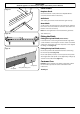
Bypass Screw Adjustment
Turn the bypass screw on each control clockwise to the stop
(Fig.8-3).
Stick on Label
Stick the LP gas label over the natural gas part of the
appliance data label.
8. Conversion to LP Gas
ArtNo.0102-0011 - Screwing
the control valve bypass screw
Fig.8-3