INSTALLATION INSTRUCTIONS HB0058 WP29M SERIES ! INTENDED FOR DOMESTIC COOKING ONLY ! READ AND SAVE THESE INSTRUCTIONS INSTALLER: LEAVE THIS MANUAL WITH HOMEOWNER. HOMEOWNER: USE, CARE AND OPERATION INFORMATION ON PAGES 10 AND 11. BEST; Hartford, Wisconsin www.BestRangeHoods.com 800-558-1711 BEST; Drummondville, QC, Canada www.BestRangeHoods.com 866-737-7770 REGISTER YOUR PRODUCT ON LINE AT: www.BestRangeHoods.com/register For additional information - visit www.BestRangeHoods.com SV07693 rev.
! WARNING ! WARNING TO REDUCE THE RISK OF FIRE, ELECTRIC SHOCK OR INJURY TO PERSONS, OBSERVE THE FOLLOWING: TO REDUCE THE RISK OF INJURY TO PERSONS IN THE EVENT OF A RANGE TOP GREASE FIRE, OBSERVE THE FOLLOWING*: 1. Use this unit only in the manner intended by the manufacturer. If you have questions, contact the manufacturer at the address or telephone number listed in the warranty. 1. 2.
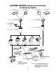
- WP29M SERIES RANGE HOOD SYSTEM INTERIOR BLOWERS Model 437 (High capacity roof cap) Model 441 (10’’ Round wall cap) Model 647 (7” Round wall cap) Model 634 or 644 (roof cap) Model 415 (7” round adjustable elbow) Model 418 (10” round adjustable elbow) Model 421 (10” Round Vertical In-line damper — Optional) Model 407 (7” round duct—2 ft. sections) Model 410 (10” round duct—2 ft.
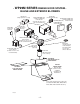
- WP29M SERIES RANGE HOOD SYSTEM IN-LINE AND EXTERIOR BLOWERS Model 437 (High capacity roof cap) Model ILB9 (800 cfm) or ILB11 (1100 cfm) in-line blower (includes two 8” x 12” to 10’’ round transitions) Model 441 (10” Round wall cap) Model EB12 (1200 cfm) or EB15 (1500 cfm) exterior blower Model EB6 (600 cfm) or EB9(900 cfm) exterior blower Model 441 (10” Round wall cap) Model 643 (8” Round wall cap) Model ILB6 (600 cfm) in-line blower (includes two 4½” x 18½” to 10’’ round transitions) Model ILB3 (
1. SELECT BLOWER OPTION AND INSTALLATION TYPE 1.1 NON-DUCTED INSTALLATION For a non-ducted installation, we recommend using interior blower Best model P6 for effectiveness. (Blower sold separately.) The non-duct kit ANKWP Series (sold separately) must be installed. This kit fits hood from 30-inch width up to 48-inch width. See installation instructions included with the non-duct kit ANKWP Series. 1.
2. MEASURE INSTALLATION Dimensions for the most common installation are shown beside. The minimum hood distance above cooktop must not be less than 24’’. A maximum of 30” above cooktop is highly recommended for best capture of cooking impurities. Distances over 30” are at the installer and users discretion. Ceiling Cabinet, soffit, decorative flue or non-duct kit flue A Top of wood mounting strip A + 0.
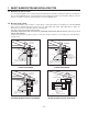
4. REMOVE THE FILTERS AND THE GREASE DRIP RAIL(S) 1 A. Remove tape on filters. Remove filters from hood and set aside. NOTE: It is recommended to start with the central one. B. Remove tape on grease drip rail (1). Lift out grease drip rail and set aside. NOTE: The 60-inch width hood has 2 grease drip rails. HD0175 5. REMOVE THE PAN Using a Phillips no. 2 or Robertson no. 2 screwdriver, remove the screws retaining the pan (shaded part on illustration beside) to the hood. Remove the pan and set aside.
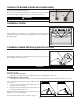
. INSTALL THE HOOD Rest the top back cavity of the hood on the wood mounting strip. CAUTION Hold the hood until it is completely secured to the wood mounting strip. TOP MOUNTING Secure the hood to wood mounting strip with (4) screws no. 8 x 3/4” (for 30” and 36” width hoods) or (6) screws (for 42” width and wider hoods) provided at locations shown. Drill (2) 3/16’’ size holes into the drywall for wall anchors through the existing holes in the inside hood back in the locations shown.
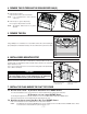
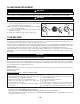
13.INSTALL THE BLOWER (INTERIOR OR EXTERIOR BLOWER) Refer to instructions included with blower. Once the blower is installed, plug the blower cord (A) into the female receptacle and the power supply cord (B) onto the male connector inside the hood. A B ! WARNING Do not plug the two cords into each other. HE0078 14.REINSTALL THE PAN Using a Phillips no. 2 or Robertson no.
16.LIGHT BULBS REPLACEMENT ! WARNING In order to prevent the risk of personal injury, do not install a lamp identified for use only in enclosed fixtures. This hood must use 120 V, 50 W, MR16 with GU10 base or PAR16 with GU10 base, shielded halogen lamps (included). ! WARNING In order to prevent the risk of personal injury, the halogen lamps must be cooled down before removing them. 1 1. To remove lamps, gently push upwards and turn counterclockwise to disengage bulb leads from their grooves.
18.OPERATION Always turn ON your hood before you begin cooking in order to establish an air flow in the kitchen. Let the blower run for a few minutes to clear the air after you turn off the range. This will help keep the whole kitchen cleaner and brighter. 2 1 3 4 HC0030 1. ON/OFF Blower switch 2. Blower speed control 3. ON/OFF Halogen light switch 4. Light intensity control Blower The blower is operated using two (2) controls.
SERVICE PARTS 7 4 8 3 1 5 2 6 11 10 12 9 14 13 HL0083 WP29XX4 MODEL KEY NO.