RMG1H60SG RMG1H90SG Instructions Manual www.rangemaster.co.
Instructions Manual INDEX RECOMMENDATIONS AND SUGGESTIONS ......................................................................................................................3 CHARACTERISTICS..............................................................................................................................................................4 INSTALLATION ..................................................................................................................................................
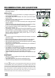
RECOMMENDATIONS AND SUGGESTIONS The Instructions for Use apply to several versions of this appliance. Accordingly, you may find descriptions of individual features that do not apply to your specific appliance. INSTALLATION • The manufacturer will not be held liable for any damages resulting from incorrect or improper installation. • The minimum safety distance between the cooker top and the extractor hood is 450 mm.
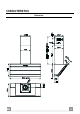
CHARACTERISTICS Dimensions EN 4 4
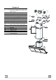
Components Q.ty Product Components 1 Hood Body, complete with: Controls, Light, Blower, Filters 2 1 Telescopic Chimney comprising: 2.1 1 Upper Section 2.2 1 Lower Section 9 1 Reducer Flange ø 150-120 mm 10 1 Adapting ring ø 120-125 mm 14.1 2 Air Outlet Connection Extension 15 1 Air Outlet Connection Ref. Q.ty Installation Components 7.2.1 2 Upper Chimney Section Fixing Brackets 7.3 1 Air Outlet Connection Support 11 6 Wall Plugs 12a 6 Screws 4,2 x 44,4 12c 6 Screws 2,9 x 9,5 Q.
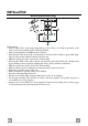
INSTALLATION 1÷2 Wall drilling and bracket fixing 11 X 7.2.1 116 116 1040 450 mm min 12a Wall marking: • Draw a vertical line on the supporting wall up to the ceiling, or as high as practical, at the centre of the area in which the hood will be installed. • Draw a horizontal line at 1040 mm above the hob. • Place bracket 7.2.1 on the wall as shown about 1-2 mm from the ceiling or upper limit aligning the centre (notch) with the vertical reference line.
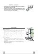
Mounting the hood body • Before attaching the hood body, tighten the two screws Vr located on the hood body mounting points. • Hook the hood body onto the screws 12a. • Fully tighten support screws 12a. • Adjust screws Vr to level the hood body. Vr 12a Connections DUCTED VERSION AIR EXHAUST SYSTEM When installing the ducted version, connect the hood to the chimney using either a flexible or rigid pipe ø 150 or 125 mm, the choice of which is left to the installer.
ELECTRICAL CONNECTION • Connect the hood to the mains through a two-pole switch having a contact gap of at least 3 mm. • Remove the grease filters (see paragraph Maintenance) being sure that the connector of the feeding cable is correctly inserted in the socket placed on the side of the fan. 7.2.1 Flue assembly Upper exhaust flue • Slightly widen the two sides of the upper flue and hook them behind the brackets 7.2.1, making sure that they are well seated.
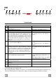
USE A B C D F E G H I L Control board Key Function A Switches the extractor motor on and off at the latest selected speed B Decreases the suction speed. C Increases the suction speed. D By pressing this key it is possible to start the intensive speed from any previously selected speed except the Delay-function and 24H-function. This speed has been timed at 10 minutes. After that time the system activates automatically the latest selected speed.
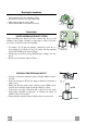
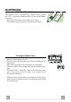
MAINTENANCE REMOTE CONTROL (OPTIONAL) The appliance can be controlled using a remote control powered by a 1.5 V carbon-zinc alkaline batteries of the standard LR03AAA type. • Do not place the remote control near to heat sources. • Used batteries must be disposed of in the proper manner. Cleaning the Comfort Panels • Pull the Comfort Panel to open it. • Disconnect the panel from the hood canopy by sliding the fixing pin lever. • The comfort panel must never be washed in a dishwasher.
Metal grease filters Metal filters can be washed also in a dish machine. They need to be washed every time a drop-symbol appears in the display or at least every two months. In case of very frequent use these have to be washed even more often. Alarm reset • Press the G-key for at least 2 seconds. Cleaning • Open the comfort panel. • Remove the filters one by one by pushing them backwards and pulling them down contemporaneously. • Wash the filters. Pay attention not to bend them.
Charcoal filter (recycling version) This filter cannot be washed or regenerated. It must be replaced when the C appears on the display or at least once every 4 months. The filter saturation alarm has to be activated already before. Activation of the alarm signal • In the recycling version hoods the filter saturation alarm must be activated during the installation or later. • Switch off the hood and the lights.
AGA RANGEMASTER LTD.