RMG2H60SS RMG2H90SS Instructions Manual www.rangemaster.co.
Instructions Manual INDEX RECOMMENDATIONS AND SUGGESTIONS ......................................................................................................................3 CHARACTERISTICS..............................................................................................................................................................4 INSTALLATION ..................................................................................................................................................
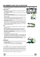
RECOMMENDATIONS AND SUGGESTIONS The Instructions for Use apply to several versions of this appliance. Accordingly, you may find descriptions of individual features that do not apply to your specific appliance. INSTALLATION • The manufacturer will not be held liable for any damages resulting from incorrect or improper installation. • The minimum safety distance between the cooker top and the extractor hood is 450 mm.
CHARACTERISTICS Dimensions EN 4 4
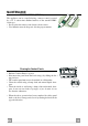
Components Q.ty Product Components 1 Hood Body, complete with: Controls, Light, Blower, Filters 2 1 Telescopic Chimney comprising: 2.1 1 Upper Section 2.2 1 Lower Section 9 1 Reducer Flange ø 150-120 mm 10 1 Adapting ring ø 120-125 mm 14.1 2 Air Outlet Connection Extension 15 1 Air Outlet Connection Ref. Q.ty Installation Components 7.2.1 2 Upper Chimney Section Fixing Brackets 7.3 1 Air Outlet Connection Support 11 6 Wall Plugs 12a 6 Screws 4,2 x 44,4 12c 6 Screws 2,9 x 9,5 Q.
INSTALLATION 1÷2 Wall drilling and bracket fixing 11 X 7.2.1 116 116 1040 450 mm min 12a Wall marking: • Draw a vertical line on the supporting wall up to the ceiling, or as high as practical, at the centre of the area in which the hood will be installed. • Draw a horizontal line at 1040 mm above the hob. • Place bracket 7.2.1 on the wall as shown about 1-2 mm from the ceiling or upper limit aligning the centre (notch) with the vertical reference line.
Mounting the hood body • Before attaching the hood body, tighten the two screws Vr located on the hood body mounting points. • Hook the hood body onto the screws 12a. • Fully tighten support screws 12a. • Adjust screws Vr to level the hood body. Vr 12a Connections DUCTED VERSION AIR EXHAUST SYSTEM When installing the ducted version, connect the hood to the chimney using either a flexible or rigid pipe ø 150 or 125 mm, the choice of which is left to the installer.
ELECTRICAL CONNECTION • Connect the hood to the mains through a two-pole switch having a contact gap of at least 3 mm. • Remove the grease filters (see paragraph Maintenance) being sure that the connector of the feeding cable is correctly inserted in the socket placed on the side of the fan. 7.2.1 Flue assembly Upper exhaust flue • Slightly widen the two sides of the upper flue and hook them behind the brackets 7.2.1, making sure that they are well seated.
USE S1 L T1 T2 T3 T4 Control Panel The hood can be switched on pushing directly onto the requested speed without firstly having to select 0/1 button. KEY LED FUNCTIONS L 0/1 Light Turns lighting on and off. T1 0/1 Motor on First speed. When pressed for about 1 seconds the motor is switched off. T2 Speed on Second speed. T3 Speed on Third speed. T4 Speed Fixed Max. speed Flashing Intensive speed. Suitable for the strongest cooking vapours and odours.
MAINTENANCE REMOTE CONTROL (OPTIONAL) The appliance can be controlled using a remote control powered by a 1.5 V carbon-zinc alkaline batteries of the standard LR03AAA type. • Do not place the remote control near to heat sources. • Used batteries must be disposed of in the proper manner. Cleaning the Comfort Panels • Pull the Comfort Panel to open it. • Disconnect the panel from the hood canopy by sliding the fixing pin lever. • The comfort panel must never be washed in a dishwasher.
Grease filters CLEANING METAL SELF- SUPPORTING GREASE FILTERS Alarm signal reset • Switch off the lights and extractor motor. • Press button T3 for at least 3 seconds, until the leds start to flash. Cleaning the filters • The filters are washable and must be cleaned at least every 2 months of operation, or more frequently for particularly heavy usage. • Pull the Comfort Panel to open it. • Remove the filters one at a time by pushing them towards the back of the group and pulling down at the same time.
Activated charcoal filter (Recirculation version) The filter is not washable and cannot be regenerated. It must be replaced when led S1 flashes or at least every 4 months. The alarm signal will only light up when the extractor motor is switched on. Alarm signal activation • In Recirculation version Hoods, the Filter saturation alarm can be enabled on installation or at a later date. Turn the Lights and the suction Motor off.
AGA RANGEMASTER LTD.