INSTALLATION INSTRUCTIONS HB0031 MODELS RMIP33 ! AND RMIP45 INTENDED FOR DOMESTIC COOKING ONLY ! READ AND SAVE THESE INSTRUCTIONS INSTALLER: LEAVE THIS MANUAL WITH HOMEOWNER. HOMEOWNER: USE AND CARE INFORMATION ON PAGES 12 AND 13. Broan-NuTone LLC; Hartford, Wisconsin www.broan.com 800-558-1711 Broan-NuTone Canada; Mississauga, Ontario www.broan.ca 877-896-1119 REGISTER YOUR PRODUCT ON LINE AT: www.broan.com/register SV05861 rev.
! WARNING ! WARNING TO REDUCE THE RISK OF FIRE, ELECTRIC SHOCK OR INJURY TO PERSONS, OBSERVE THE FOLLOWING: TO REDUCE THE RISK OF INJURY TO PERSONS IN THE EVENT OF A RANGE TOP GREASE FIRE, OBSERVE THE FOLLOWING*: 1. Use this unit only in the manner intended by the manufacturer. If you have questions, contact the manufacturer at the address or telephone number listed in the warranty.
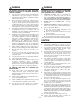
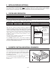
- RMIP33 AND RMIP45 INSERT SYSTEM INTERIOR BLOWERS Model 647 (7” Rd wall cap) Model 643 (8” Rd wall cap) Model 634 or 644 (roof cap) Model 415 7” Rd adjustable elbow (optional) 8” Rd adjustable elbow (optional) 8” Rd standard duct Model 407 (7” Rd x 24’’ section) 8” Rd metal flexible duct (optional) 7” Rd metal flexible duct (optional) Model 412 transition (3¼” x 10” to 7”) Model 413 transition (3¼” x 10” to 8”) Adapter and damper 3¼’’ x 10’’ (supplied with P5 and P8 blowers) Model 459 transitio
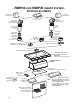
- RMIP33 AND RMIP45 INSERT SYSTEM IN-LINE AND EXTERIOR BLOWERS Model 437 (High capacity roof cap) Model HLB9 (800 cfm) or HLB11 (1100 cfm) in-line blower (includes two 8” x 12” to 10’’ round transitions) Model 441 (10” Rd wall cap) Model 335 (1200 cfm) or 336 (1500 cfm) exterior blower Model 331H (600 cfm) or 332H (900 cfm) exterior blower Model 441 (10” Rd wall cap) Model 643 (8” Round wall cap) Model HLB6 (600 cfm) in-line blower (includes two 4½” x 18½” to 10’’ round transitions) Model 418 10” Rd
1. SELECT BLOWER OPTION AND INSTALL DUCTWORK Either an interior or exterior blower or in-line blower may be used with this insert. The insert model RMIP33 or RMIP45 must be installed with blower models P5, P8, HLB3, HLB6, HLB9, HLB11, 331H, 332H, 335 or 336 only. Other blowers cannot be substituted. (Blowers sold separately). Plan where and how the ductwork will be installed. Access to the top of the hood is preferred for connection of ductwork. As an alternative, flexible metal ductwork may be used.
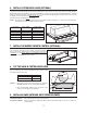
3. INSTALL BACKSPLASH (OPTIONAL) It is recommended to install the backsplash before the custom hood insert. The custom hood will cover the backsplash top mounting screws. In order to be able to install the backsplash, make sure you have at least 18’’ clearance between bottom of custom hood and range control panel or cooktop. (See instructions packed with backsplash.) 4. CUSTOM HOOD PREPARATION ! WARNING When building a custom hood, always follow all applicable construction codes and standards.
6. INSTALL CUSTOM HOOD LINER (OPTIONAL) The liners are specially designed to protect the exterior base of the custom hood. To order, refer to the table below to find the right liner model number for your insert and width of custom hood. To view specific model information, including depths for each liner models, visit www.broan.com or contact Technical Support (phone number listed on front cover). To install, see instruction packed with custom hood liner. The liner must be installed before the insert.
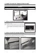
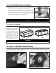
10. REMOVE THE KNOCK-OUT OPENING (INTERIOR BLOWER) Remove the knockout on rough-in plate. See picture below. CAUTION When using P5 blower, remove the 10’’ wide knockout (smaller part). If using P8 blower, remove the knockout corresponding to the ducting installed (10’’ or 14’’ adapter/damper). UT CKO NO 14’’ K OUT OCK KN 10’’ HD0077 Removing vertical knockout opening on rough-in plate 11. INSTALL THE DEVIATOR (INTERIOR BLOWER) Install the deviator as shown.
13. CONNECT WIRING (ALL BLOWERS) ! WARNING Risk of electrical shock. Electrical wiring must be done by qualified personnel in accordance with all applicable codes and standards. Before connecting wires, switch power off at service panel and lock service disconnecting means to prevent power from being switched on accidentally. Position insert below the installed custom hood. Pull cable through hole in top of insert. INTERIOR BLOWER: Remove the cable knock-out on the top of the rough-in plate.
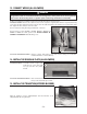
16. DUCTING CONNECTION (ALL BLOWERS) A. When there is access to the top of the hood, connect ductwork and seal connections with duct tape after Step 17 Install the insert. B. When there is no access to the top of the hood, carefully pull down the metal duct through the custom hood base hole. Slide this duct over the transition (interior blower) or over the flange of the rough-in plate (in-line or exterior blower). Make sure the adapter/damper assembly enters the ducting.
18. INSTALL THE BLOWER (INTERIOR BLOWER) (CONT’D) Install (4) no. 8 x 3/8’’ screws into the location as shown in the pictures below (single blower or dual blower). Do not tighten screws down fully, leave a 1/8” gap. Hang blower unit onto blower plate (screws through the large part of the keyhole). Slide the blower to its position (screws in the small part of the keyhole). Tighten the (4) screws. HD0044 HD0045 Dual blower (P8) Single blower (P5) Secure the blower by installing 2 more no.
19. LIGHT BULBS This insert uses 50 W halogen lamps (120 V, 50 W, PAR 20) (Purchase separately). Install the lamps by rotating them clockwise into their socket holder. 20. INSTALL FILTERS It is recommended to install side filters first and finish with center one(s). 1.Insert upper end of filter into the insert (finger sized cup side). 2.Raise lower end of filter to position it into grease rail inside of hood and pull. 3.While pulling the filter, slide it under the inner retaining piece.
21. USE AND CARE (CONT’D) Avoid: when choosing a detergent - Any cleaners that contain bleach will attack stainless steel. - Any products containing : chloride, fluoride, iodide, bromide will deteriorate surfaces rapidly. - Any combustible products used for cleaning such as acetone, alcohol, ether, benzol, etc., are highly explosive and should never be used close to a range. 22. OPERATION Always turn your blower on before you begin cooking to establish an air flow in the kitchen.
WARRANTY ONE YEAR LIMITED WARRANTY FOR BROAN ELITE PRODUCTS Broan-NuTone LLC (Broan-NuTone) warrants to the original consumer purchaser of Broan Elite products that such products will be free from defects in materials or workmanship for a period of one year from the date of original purchase. THERE ARE NO OTHER WARRANTIES, EXPRESS OR IMPLIED, INCLUDING, BUT NOT LIMITED TO, IMPLIED WARRANTIES OR MERCHANTABILITY OR FITNESS FOR A PARTICULAR PURPOSE.
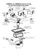
SERVICE PARTS SINGLE BLOWER/ROUGH-IN (Model P5) 1 20 21 2 23 22 19 3 4 17 5 6 8 7 18 16 15 14 13 6 12 9 11 10 HL0021 KEY NO.
SERVICE PARTS DUAL BLOWER/ROUGH-IN (Model P8) 2 1 25 3 4 24 23 22 21 5 19 18 17 16 15 14 6 7 8 11 20 9 13 10 12 HL0022 KEY NO.