ArtNo.
Contents 1. Before You Start... 1 2. Cooker Overview 3 3. Cooking Tips 11 4. Cooking Table 12 5. Cleaning Your Cooker 13 6. Troubleshooting 16 7. Installation 18 8. Servicing 22 9. Circuit Diagrams 27 10.
1. Before You Start... DocNo.015-0301 - Introduction - Induction cooker Personal Safety Thank you for buying a Falcon cooker. It should give you many years of trouble-free cooking if installed and operated correctly. It is important that you read this section before you start, particularly if you have not used an induction cooker before.
Make sure to use adequately sized pans with flat bottoms that are large enough to cover the surface of the hotplate heating area. Never leave the hotplate unattended at high heat settings. Pans boiling over can cause smoking, and greasy spills may catch on fire. Use a deep fat thermometer whenever possible to prevent fat overheating beyond the smoking point. Always LIFT pans off the hob. Sliding pans may cause marks and scratches. Always turn the control to the OFF position before removing a pan.
2. Cooker Overview DocNo.025-0009 - Overview - 110 induction - toledo � Fig.2-1 � � � � � The 110 induction cooker (Fig.2-1) has the following features: A. B. C. D. E. F. Fig.2-2 5 induction cooking zones A control panel A grill A conventional oven A programmable fan oven A storage drawer ArtNo.312-0004 Correct pans ceramic The Hob Use only pans that are suitable for induction hobs. We recommend stainless steel, enamelled steel pans or cast iron pans with enamelled bases.
Make sure that the base of the pan is clean and dry to prevent any residue burning onto the hob panel. This also helps prevent scratches and deposits. Fig.2-4 ����� ����� ����� Always use pans that are the same size as (or slightly larger than) the areas marked on the hob. Using a lid will help the contents boil more quickly. ArtNo.313-0002 - 110 induction hob rating ����� Always take care before touching the surface, even when the hob is turned off.
heat up at 100% power for a specified time before the power is reduced to the level selected. ����������� When the Automatic Heat-up function is activated, the hob control display will alternately flash between the [A ] setting and the chosen power level. Once the automatic heat-up time has ended the hob control display will stop flashing and will display the chosen power level.
For best results, you should leave the grill pan in the grill chamber and preheat the appropriate part(s) of the grill for two minutes. The grill trivet can be removed and the food placed on it while you are waiting for the grill to preheat. Fig.2-10 Once the grill has preheated, slide the grill pan out again. With the trivet back in place with the food on it, slide the grill pan back onto the side supports. Ensure that it is pushed right in. ArtNo.
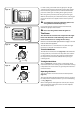
The Clock Fig.2-14 Setting the time of day The LCD clock is shown in (Fig 2-14). When the clock is first connected the display flashes ( 0.00) and ( ) alternately. Press and hold both the [] and [] buttons as shown in Fig.2-15. While holding these buttons press either the (–) or (+) until the correct time shows. Remember this is a 24-hour clock. If you make a mistake or press the wrong button, turn off the power supply for a minute or two and start again. ArtNo.
AUTO is showing, you want to reset to manual cooking Fig.2-21 When cancelling an automatic setting, any cooking time already set must be returned to ( 0.00) before you can return to manual, by pressing the () button. ArtNo.302-0008 Activating the key lock 1 Key Lock When the key lock is activated, the left-hand oven can be operated as usual but the right-hand oven is locked and will not come on. Fig.
Accessories Fig.2-27 Oven Shelves � In addition to the flat shelves (Fig.2-26), some models are supplied with a drop shelf (Fig.2-27). The drop shelf increases the possibilities for oven shelf spacing. ArtNo.320-0010 Flat & drop shelves The oven shelves can be easily removed and refitted. � Pull the shelf forward until the back of the shelf is stopped by the shelf stop bumps in the oven sides (Fig.2-28).
Main Oven Light Fig.2-34 Press the appropriate button to turn one of the lights on (Fig.2-34). If an oven light fails, turn off the power supply before changing the bulb. See the ‘Troubleshooting’ section for details on how to change the bulb. ArtNo.320-0027 - Twin oven lights The Browning Element The Browning Element is positioned in the top of the lefthand oven. It can be used at the end of a normal cooking period to give extra browning to au gratin dishes or give a crisper finish to meat. Fig.
DocNo.030-0002 - Cooking tips - electric 3. Cooking Tips Tips on Cooking with the Timer General Oven Tips If you want to cook more than one dish, choose dishes that require approximately the same cooking time. However, dishes can be ‘slowed down’ slightly by using small containers and covering them with aluminium foil, or ‘speeded up’ slightly by cooking smaller quantities or placing them in larger containers. The wire shelves should always be pushed firmly to the back of the oven.
DocNo.031-0002 4. Cooking Table The oven control settings and cooking times given in the table below are intended to be used AS A GUIDE ONLY. Individual tastes may require the temperature to be altered to provide a preferred result. Top Centre Food is cooked at lower temperature in a fan oven than in a conventional oven. When using recipes, reduce the fan oven temperature by 10°C and the cooking time by 5-10 minutes.
DocNo.045-0011 - Cleaning - 110 Induction - tpl glzd & std grill 5. Cleaning Your Cooker Isolate the electricity supply before carrying out any major cleaning. Allow the cooker to cool. Fig.5-1 Never use paint solvents, washing soda, caustic cleaners, biological powders, bleach, chlorine based bleach cleaners, coarse abrasives or salt. Do not mix different cleaning products – they may react together with hazardous results.
Once you have removed as much as possible with the scraper, follow the ‘Daily Care’ procedure outlined above. Fig.5-2 To Remove Metal Rub-off Sliding pans on the hob – especially aluminium or copper pans – can leave marks on the surface. These marks often appear like scratches, but can easily be removed using the procedure described previously for ‘Cleaning spills’.
‘Cook & Clean’ Panels Fig.5-3 The main oven has side ‘Cook & Clean’ panels which have been coated with a special enamel that partly cleans itself. This does not stop all marks on the lining, but helps to reduce the amount of manual cleaning needed. These panels work better above 200°C. If you do most of your cooking below this temperature, occasionally remove the panels and wipe with a lint free cloth and hot soapy water.
DocNo.055-0002 - Troubleshooting - Induction 6. Troubleshooting The cooling fan The induction hob incorporates a cooling fan. This cooling fan is active when either the grill or ovens are on. Under certain conditions, the cooling fan may remain active when the grill or ovens are switched off. This is normal and the fan will switch off automatically. Interference with and repairs to the hob MUST NOT be carried out by unqualified persons.
Food is cooking too slowly, too quickly, or burning Cooking times may differ from your previous oven. Check that you are using the recommended temperatures and shelf positions – see the oven cooking guide. Then adjust the settings according to your own individual tastes. Before removing the existing bulb, turn off the power supply and ensure that the oven is cool. Open the oven door and remove the oven shelves. Locate the bulb cover and unscrew it by turning it anticlockwise (it may be very stiff ).
DocNo.065-0002 - Installation - 110 Induction 7. Installation Dear Installer Location of Cooker Before you start your installation, please complete the details below, so that, if your customer has a problem relating to your installation, they will be able to contact you easily. The cooker may be installed in a kitchen/kitchen diner but NOT in a room containing a bath or shower. This appliance is designed for domestic cooking only.
Positioning the Cooker Fig.7-1 Fig.7-1 shows the minimum recommended distance from the cooker to nearby surfaces. ���� ��� The cooker should not be placed on a base. ����� ��� ���� ��� The hotplate surround should be level with, or above, any adjacent work surface. A gap of 75mm should be left between each side of the cooker ABOVE the hotplate level and any adjacent vertical surface.
Fig.7-6 LOWER THE FRONT ROLLER by doing 14 complete (360°) turns clockwise (Fig.7-6). (This means turning and removing the levelling tool 56 times). ���� Now LOWER THE TWO REAR ROLLERS. First fit the levelling tool on the hexagonal adjusting nut (Fig.7-7). Make 10 complete (360º) turns clockwise (Fig.7-8). (This means turning and removing the levelling tool 20 times.) ArtNo.010-0008 Lowering the front rollers Make sure you lower BOTH REAR ROLLERS.
clockwise to raise the cooker and anticlockwise to lower. Fig.7-11 When you are satisfied with the height and level, raise the front of the cooker by one turn of the front roller adjuster. Screw down the front feet to meet the floor. Screw the front roller adjuster anticlockwise to raise the front roller so that the front of the cooker is supported on the feet, not the front roller, to prevent accidental movement of the cooker.
WARNING – SERVICING TO BE CARRIED OUT ONLY BY AN AUTHORISED PERSON Disconnect from electricity before servicing. Check appliance is safe when you have finished. 8. Servicing Fig.8-1 ArtNo.210-0008 - Classic Removing the end caps Disconnect the cooker from the electricity supply before servicing, particularly before removing any of the following: control panel, side panels, ceramic hob, or any of the electrical components or cover boxes.
WARNING – SERVICING TO BE CARRIED OUT ONLY BY AN AUTHORISED PERSON Disconnect from electricity before servicing. Check appliance is safe when you have finished. 5. To Replace a Light Switch Fig.8-2 Disconnect from electricity supply. Fig.8-3 Remove the control panel (see 3). Note: The old switch may be destroyed during removal. Remove the old switch from its bezel by gripping the switch body behind the control panel and twisting sharply.
WARNING – SERVICING TO BE CARRIED OUT ONLY BY AN AUTHORISED PERSON Disconnect from electricity before servicing. Check appliance is safe when you have finished. Note: The arms are spring tensioned. Carefully remove the grill door. Retain the gaskets. Fig.8-4 Reassemble in reverse order ensuring that the gasket is fitted between the hinge arm and the front of the grill chamber. 9. Disconnect from electricity supply. ArtNo.
WARNING – SERVICING TO BE CARRIED OUT ONLY BY AN AUTHORISED PERSON Disconnect from electricity before servicing. Check appliance is safe when you have finished. 14. To Change the Oven Door Latch Fig.8-7 Remove the outer door panel (see 13). Remove screws ‘B’ that hold the latch assembly to the inner door panel (Fig.8-7). Fit the new catch and reassemble in reverse order. Fig.8-8 ArtNo.320-0004 Oven door keep Verify the door operation. 15.
WARNING – SERVICING TO BE CARRIED OUT ONLY BY AN AUTHORISED PERSON Disconnect from electricity before servicing. Check appliance is safe when you have finished. 20. To Replace an Oven Fan Fig.8-12 Disconnect from electricity supply. Pull the cooker forward to gain access to the rear. Remove the screws securing the electric cover to the back sheet and remove the cover. ArtNo.322-0002 Oven bottom element access � � Disconnect the three terminals connected to the fan noting their position.
DocNo.095-0002 - Circuit diagram - 110 Induction 9. Circuit Diagram: Oven � �� � � � ArtNo.
Circuit Diagram: Hob To T1 To T2 MCB MCB br br br To Earth MCB To T4 To T5 MCB MCB b b b g/y br g/y br b b br b CU1 g/y b CU2 br br g/y br b 2.3kW r b b CU3 r br b 2.3kW 1.4kW b r 2.3kW b 1.
DocNo.105-0002 - Technical data - 110 Induction 10. Technical Data INSTALLER: Please leave these instructions with the User. DATA BADGE LOCATION : Cooker back, serial number repeater badge below oven door opening. Connections Electric 220 - 240V 50Hz Dimensions Overall height minimum 902mm maximum 927mm Overall width 1100mm Overall depth 650mm Refer to 'Positioning the Cooker'. Ratings ����� ����� ����� ArtNo.
DocNo.000-0001 - Back cover Rangemaster ���������������������������������������� ArtNo.000-0003 CE logo www.rangemaster.co.