
User's Manual


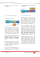
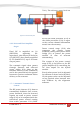
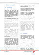
Table Of Contents
- 4. - ST-3118 RF DESCRIPTION
- 4.1. Circuit Configuration
- 4.2. Receiver System
- 4.2.1. Front-end RF Receiver
- 4.2.2. ANALOG Audio Processing
- 4.2.3. Virtual Squelch Circuit
- 4.2.4. Virtual VOLUME CONTROL
- 4.2.5. Sub audio signaling
- 4.2.6. ANALOG AUDIBLE SIGNALING
- 4.2.7. DIGITAL AUDIO PROCESSING
- 4.3. Transmitter System
- 4.3.1. ANALOG TX SIGNAL
- 4.3.2. DIGITAL TX AUDIO:
- 4.3.3. Drive and Final Amplifier Stages
- 4.3.4. Automatic Transmit Power Control
- 5. ST-3118 ALIGNMENT
- 5.1. Introduction
- 5.2. ALIGNMENT:
- 5.3. Required Test Equipment
- 5.4. Alignment Procedure
- 5.4.1. GENERAL ALIGNMENT CONSIDERATIONS:
- 5.5. MAIN RADIO ALIGNMENT
- 5.6. TRANSMITTER ALIGNMENT:
- 5.6.1. Main Clock alignment:
- 5.6.2. Transmit Power alignment:
- 5.6.2.1. High POWER LEVEL ALIGNMENT
- 5.6.2.2. Mid POWER LEVEL ALIGNMENT
- 5.6.2.3. LOW POWER LEVEL ALIGNMENT
- 5.6.3. ANALOG MAXIMUM DEVIATION
- 5.6.4. Modulation Gain alignment:
- 5.6.5. FDMA DATA MODULATION alignment:
- 5.6.6. TDMA DATA MODULATION alignment:
- 5.6.7. EIA tones Level Alignment:
- 5.6.8. DTMF signaling level alignment:
- 5.6.9. DCS signaling alignment:
- 5.6.10. CTCSS signaling alignment
- 5.6.11. FSK signaling alignment:
- 5.7. RECEIVER ALIGNMENT
- 5.7.1. DISCRIMINATOR GAIN
- 6. COMPLIMENTARY USER ALIGNMENT
- 6.1. OPTION ALIGNMENT:
- 6.1.1. ANALOG Microphone gain:
- 6.1.2. ANALOG External Mic Gain:
- 6.1.3. Analog AGC
- 6.1.4. DIGITAL AGC
- 6.1.5. MINIMUM VOLUME LEVEL:
- 6.1.6. SQUELCH LEVEL:
- 6.1.7. DISABLE RF POWER
- 7. RADIO APPEARANCE ALIGNMENT
- 7.1. DISPLAYS AND LEDS:
- 7.1.1. Auto backlight delay alignment:
- 7.1.2. Power on Text:
- 7.1.3. Leds:
- 7.2. Tones
- 7.3. ANNUNCIATION

4. - ST-3118 RF DESCRIPTION
4.1. Circuit Configuration
The receiver is a single receiver with
built DSP fully integrated.
Incoming signals from the antenna,
after passing through LPF filter, are
fed direct to the DSP down
converter to get the baseband voice
from 0Hz to 3500Hz.
Demodulated signals are filtered
and conditioned onto a second DSP
based filter, which also includes a
high efficiency 4FSK modem.
For digital demodulation, the
recovered data is fed into a vocoder,
which converts the data to voice.
Analog voice form the analog path
or the analog voice recovered from
the vocoder are fed into an audio
power amplifier.
The transmit signal frequency is
generated by the integrated VCO
and PLL. RF frequency generated by
the integrated RF chip is amplified
into a 3-step amplifier then filtered
by a low pass filter to be applied to
the antenna.
4.2. Receiver System
4.2.1. Front-end RF Receiver
Incoming RF signals from the
antenna are delivered to the
Receiver Unit and pass through a
Low-pass filter, antenna switching
diodes, and then fed to the receiver
(U2) passing through a limiter BPF.
4.2.2. ANALOG Audio Processing
The RF signal is tuned by U2, which
includes a base band DSP audio
processing, recovering flat audio
from DC up to 3500 hz.
The detected audio is amplified,
filtered and conditioned inside of
U12 which also includes a de-
emphasize filtering shape for
received audio signals
The output of the filtered and
conditioned audio is delivered to a
power amplifier (U8) then to the
speaker passing through the
external audio connector switch.
4.2.3. Virtual Squelch Circuit
RSSI is measured by the receiver
(U2) as the result of the analysis of
the signal and the noise of the
carrier. The output is sent to the
main processor (U13) as a digital
frame, which is analyzed by radio
firmware. If the signal quality is
higher than the expected for the
current programmed squelch
threshold, then the processor
LPF
SWITCH
PROTECTION
FILTER
RECEIVER
[U2]
RECEIVER
[U2]
AUDIO
PROCESSOR
[U12]
AMPLIFIER
[U8]
Figure 1: Receiver block Diagram
Figure 2: Receiver Analog Audio Path Bloc Diagram