
User's Manual


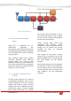
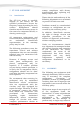
Table Of Contents
- 4. - ST-3118 RF DESCRIPTION
- 4.1. Circuit Configuration
- 4.2. Receiver System
- 4.2.1. Front-end RF Receiver
- 4.2.2. ANALOG Audio Processing
- 4.2.3. Virtual Squelch Circuit
- 4.2.4. Virtual VOLUME CONTROL
- 4.2.5. Sub audio signaling
- 4.2.6. ANALOG AUDIBLE SIGNALING
- 4.2.7. DIGITAL AUDIO PROCESSING
- 4.3. Transmitter System
- 4.3.1. ANALOG TX SIGNAL
- 4.3.2. DIGITAL TX AUDIO:
- 4.3.3. Drive and Final Amplifier Stages
- 4.3.4. Automatic Transmit Power Control
- 5. ST-3118 ALIGNMENT
- 5.1. Introduction
- 5.2. ALIGNMENT:
- 5.3. Required Test Equipment
- 5.4. Alignment Procedure
- 5.4.1. GENERAL ALIGNMENT CONSIDERATIONS:
- 5.5. MAIN RADIO ALIGNMENT
- 5.6. TRANSMITTER ALIGNMENT:
- 5.6.1. Main Clock alignment:
- 5.6.2. Transmit Power alignment:
- 5.6.2.1. High POWER LEVEL ALIGNMENT
- 5.6.2.2. Mid POWER LEVEL ALIGNMENT
- 5.6.2.3. LOW POWER LEVEL ALIGNMENT
- 5.6.3. ANALOG MAXIMUM DEVIATION
- 5.6.4. Modulation Gain alignment:
- 5.6.5. FDMA DATA MODULATION alignment:
- 5.6.6. TDMA DATA MODULATION alignment:
- 5.6.7. EIA tones Level Alignment:
- 5.6.8. DTMF signaling level alignment:
- 5.6.9. DCS signaling alignment:
- 5.6.10. CTCSS signaling alignment
- 5.6.11. FSK signaling alignment:
- 5.7. RECEIVER ALIGNMENT
- 5.7.1. DISCRIMINATOR GAIN
- 6. COMPLIMENTARY USER ALIGNMENT
- 6.1. OPTION ALIGNMENT:
- 6.1.1. ANALOG Microphone gain:
- 6.1.2. ANALOG External Mic Gain:
- 6.1.3. Analog AGC
- 6.1.4. DIGITAL AGC
- 6.1.5. MINIMUM VOLUME LEVEL:
- 6.1.6. SQUELCH LEVEL:
- 6.1.7. DISABLE RF POWER
- 7. RADIO APPEARANCE ALIGNMENT
- 7.1. DISPLAYS AND LEDS:
- 7.1.1. Auto backlight delay alignment:
- 7.1.2. Power on Text:
- 7.1.3. Leds:
- 7.2. Tones
- 7.3. ANNUNCIATION

ST-3118V SM R 1.1 SMARTRUNK SYSTEMS, INC.
11
4.3.3. Drive and Final Amplifier
Stages
Final RF is amplified on Q1
(2SC5226) adjusting the
impedance, then filtered to be fed to
Q2 (2SC3357) then finally amplified
by U3 (RA60H1317) up to 50 watts
output power.
The transmit signal then passes
through Forward and reflected
power bridge (U1), then to the
antenna switch D1/D2 (UM9401F)
and is low-pass filtered to suppress
harmonic spurious radiation before
delivery to the antenna.
4.3.4. Automatic Transmit Power
Control
The RF power detector (U1) detects
transmitted feedback and reverse
power feedback, then the detected
signals are send to power control
stage (U10) to be compared with the
referenced power control coming
from audio processor U12 (CMX-
7141). The reference power level are
set my the main processor (U13) to
the audio processor (U12) in agree
to the current channel information
stored into the memory.
Power control stage (U10) also
compares the reverse power
feedback coming from power meter
bridge (U1) to protect the power
module in case of antenna
mismatching.
The output of the power control
stage (U10) is fed direct to the RF
power Amplifier (U3) controlling the
DC bias import for the hybrid
module.
Evenly when power level is adjusted
by software on three levels (Hi, Med,
Lo) the power value can be adjusted
to any desired value between zero
and 50Watts by the alignment
software.
LPF
Ant Sw
D1/D2/
D6
Final AMP
U3
Power
Detection
U1
Driver
Q2
Buffer
AMP
Q1
TX CTRL
[Q9 Q18]
POWER
CTRL
[U10]
Figure 6: RF transmission path