
User's Manual


- 8 -
234
5
1
Operation
(Continued)
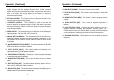
Rear Panel
1. ANTENNA : This jack accepts a 50 ohms coaxial cable in the PL- 259
type plug.
2. CW KEY : The CW key is used for Morse Code operation. To operate
this, connect a CW key to this jack, and place the mode switch in the CW
position.
3. EXTERNAL SPEAKER : This jack accepts a 4 - 8 ohm 5W external
speaker. When external speaker is connected to this jack , the built-in
speaker will be disabled.
4. PA SP. : An 8 ohm 4W PA speaker may be connected to this jack for PA
operation. Place MODE selector in PA position for this feature.
5. POWER : This accepts a 13.8 VDC power cable with built-in fuse. The
power cord provided with the radio consists of black wire (negative) and a
red wire (positive ).
- 9 -
Operation
(Continued)
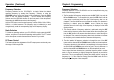
Microphone
1. PTT SWITCH : Use the Push-To-Talk (PTT) switch to control the transmit
and receive of the radio. Push to transmit and release to receive.
2. REMOTE UP/DOWN SWITCH : An operating frequency can be stepped
up or down simply by pushing either of these buttons.
For best results, the user should select a low-impedance dynamic type
microphone or a transistorized microphone.
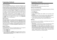
The microphone should provide the functions shown in schematic below.
6 WIRE MIC CABLE
Pin Number Mic Cable Lead
1
Audio Shield
2
Audio Lead
3
Transmit Control
4
Receive Control
5
Up Control
6
Down Control
Transceiver Microphone Schematic Diagram