SERVICE MANUAL LN-9217-00.2 A R C H IV E ADAPT AFLOWTM NODE ADAPTER ADAPTAFLOW MODEL: A10159 IMPOR TANT IMPORT ANT:: Before using this equipment, carefully read SAFETY PRECAUTIONS, starting on page 1, and all instructions in this manual. Keep this Service Bulletin for future reference. Service Manual Price: $ 20.00 (U.S.
N O T E : This manual has been changed from revision LN-9217-00.1 to revision LN-9217-00.2. Reasons for this change are noted under “Manual Change Summary” inside the back cover of this manual. ARCHIVE LN-9217-00.
AdaptaFlow Node Adapter - Contents CONTENTS PAGE 1-4 SAFETY: SAFETY PRECAUTIONS........................................................................................................... 1 HAZARDS/SAFEGUARDS........................................................................................................ 2-4 INTRODUCTION: 5-6 GENERAL DESCRIPTION......................................................................................................... 5 SPECIFICATIONS...............................
AdaptaFlow Node Adapter - Safety SAFETY SAFETY PRECAUTIONS Before operating, maintaining or servicing any ITW Ransburg electrostatic coating system, read and understand all of the technical and safety literature for your ITW Ransburg products. This manual contains information that is important for you to know and understand. This information relates to USER SAFETY and PREVENTING EQUIPMENT PROBLEMS. To help you recognize this information, we use the following symbols.
AdaptaFlow Node Adapter - Safety AREA HAZARD SAFEGUARDS Tells where hazards Tells what the hazard is. Tells how to avoid the hazard. Fire Hazard Fire extinguishing equipment must be present in the spray area and tested periodically. may occur. Spray Area Improper or inadequate operationing and maintenance pro- Spray areas must be kept clean to prevent the cedures will cause a fire hazard. accumulation of combustible residues.
AdaptaFlow Node Adapter - Safety AREA HAZARD SAFEGUARDS Tells where hazards Tells what the hazard is. Tells how to avoid the hazard. may occur. General Use and Improper operation or maintenance Personnel must be given training in accordance with may create a hazard. the requirements of NFPA-33. Maintenance Personnel must be properly trained Instructions and safety precautions must be read and in the use of this equipment. understood prior to using this equipment.
AdaptaFlow Node Adapter - Safety AREA HAZARD SAFEGUARDS Tells where hazards Tells what the hazard is. Tells how to avoid the hazard. This is a high voltage ungrounded device that can produce electrical arcs capable of igniting coating materials. Parts being sprayed must be supported on conveyors or hangers and be grounded. The resistance between the part and ground must not exceed 1 megohm. (Reference NFPA-33) may occur.
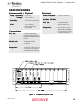
AdaptaFlow Node Adapter - Introduction INTRODUCTION GENERAL DESCRIPTION This manual covers the operation and use of the AdaptaFlowTM 5000 Node Adapter and is meant to complement the AdaptaFlow 5000 Fluid Flow Monitoring and Control Manual. The AdaptaFlow Node Adapter Module allows for direct communication from an Allen-Bradley PLC Remote Input/Output(RIO) port to the AdaptaFlow 5000 Fluid Flow Control system.
AdaptaFlow Node Adapter - Introduction SPECIFICA TIONS SPECIFICATIONS Electrical Environmental / Physical Temp.
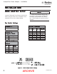
AdaptaFlow Node Adapter - Installation INST ALLA TION INSTALLA ALLATION NODE ADAPTER SETUP Jumpers E1 through E5 are factory set and should not be changed. Refer to the "Installation" documentation for the correct switch settings. NOTE > Positions 6-8 pertain to the RS-422 port which is only used by qualified ITW Ransburg representatives as a debug tool. These settings do not effect normal operation. Dip Switch Settings Position 1 RS-422 Address Always OFF Pos. 6 Pos. 7 Pos.
AdaptaFlow Node Adapter - Installation Dip Switch Settings - SW1 Rack Address Starting Quarter Rack Pos. 1 Pos. 2 Pos. 3 Pos. 4 Pos. 5 Pos.
AdaptaFlow Node Adapter - Installation NODE ADAPTER INTERF ACE SETUP INTERFACE The Node Adapter Interface board is plugged into J6 of the card rack mother board. All switches and jumpers are factory set and should not be changed, however most of these settings will not effect the operation of this board when used with AdaptaFlow systems. Figure 4: 9 Card Rack Mother Board ARCHIVE LN-9217-00.
AdaptaFlow Node Adapter - Installation An 82 ohm resistor is provided on the Interface Board to terminate the RIO cable. Where the RIO cable is daisy-chained to more than one Node Adapter, only the last connection point in the daisy-chain should be terminated by moving the associated switch to the “TERM” position. Figure 5: Node Adapter Interface PLC Remote I/O Cable Connections From PLC I/O Cable To Node Adapter Interface (RIO) Blue Shield Clear BLU SHLD CLR LN-9217-00.
AdaptaFlow Node Adapter - Operation OPERA TION OPERATION Low Rate Limit Alarm DISCRETE I/O The Node Adapter Card communicates with AllenBradley PLC's using remote I/O protocol. Two types of data are used; discrete inputs and outputs, and Block Transfer Data. Discrete I/O: There are two words of discrete inputs and two words of discrete outputs for each flow controller. These are assigned to words 1 and 2 of the Node Adapter's rack address. Word 0 is not used.
AdaptaFlow Node Adapter - Operation Input Word 1 Input Word 2 Bit Description Bit Description 00 01 02 03 04 05 06 07 08 09 10 11 12 13 14 15 CPU OK Channel #1 First Powerup Flag Channel #1 Closed Loop Channel #1 Setpoint Achieved Channel #1 Low Rate Limit Alarm Channel #1 High Rate Limit Alarm Channel #1 Total Flow Limit 1 Alarm Channel #1 Total Flow Limit 2 Alarm Channel #1 CPU OK Channel #2 First Powerup Flag Channel #2 Closed Loop Channel #2 Setpoint Achieved Channel #2 Low Rate Limit Alarm Chan
AdaptaFlow Node Adapter - Operation BLOCK TRANSFER I/O There are several words of data that must be sent and received via block transfers to and from the flow controller. The block transfer write can contain three types of information: (1) normal (configuration word 0, 1 or 2), (2) global (configuration word 3) and (3) color (configuration word 4). Normal block transfer write (BTW) data consist of the setpoint for each of the four channels.
AdaptaFlow Node Adapter - Operation Color Number For Channel No. X Rate Display Engineering Units For KFR Tells the flow controller what color table to operate out of. There are up to 32 color tables for each channel. This parameter is a three byte variable programmed in ASCII. This parameter is used by the DM-3000 to indicate engineering units for the real time flow rate display. Any ASCII characters can be programmed here. Channel No.
AdaptaFlow Node Adapter - Operation Sample Amount This parameter determines the update time that the PID control loop utilizes to read the flow meter feedback data. This parameter will have an effect on how fast the PID loop compensates for differences in fluid deliveries. The sample amount is used in a digital filter formula to calculate the actual rate. The update for the rate will become slower as this value is increased.
AdaptaFlow Node Adapter - Operation Volts 2 Gain This parameter is used to scale the spare analog output. This value acts as a multiplier to the memory location. Flow Rate Limit 1 This parameter sets the value of the trip point for flow rate alarm No. 1. Flow Rate Limit 2 Volts 2 Shifter This parameter scales the spare analog output. It acts as a divider to the memory location. For Node Adapter systems, this parameter should be set to 0.
AdaptaFlow Node Adapter - Operation Channel Number Global BTW Word Configuration The Channel number is set to 1-4 to indicate which channel is to store the data that is to follow. Word # Description 0 1 2 3 4 5 6 7 8 9 10 11 12 13 14 15 16 17 18 19 20 21 22 23 24 25 26 27 Configuration Word (3) Channel No. (1-4) KFR Factor Rate Display Eng. Unit (cc) Rate Display Eng. Unit (M) KFR DP Data KFT Factor Total Display Eng. Unit (cc) Total Display Eng.
AdaptaFlow Node Adapter - Operation Analog Out No. X These parameters represent the 10 table values stored that designate what analog output value achieves the corresponding cc/min. The value ranges from 0 to 4095 and corresponds to an analog output of 0-10 VDC. CC/MIN. No. X These parameters represent the values that the flow controller stores when a new point is stored. It corresponds to an Analog Out value. Color Data BTW Word Configuration Word # Description Configuration Word (4) Channel No.
AdaptaFlow Node Adapter - Operation Normal Data BTR Word Configuration Global Data Block T ransfer Transfer Read Operational Descriptions Word # Description 0 Configuration Word (0) Channel No. (1-4) 1 Color No. (1-32) 2 3 Actual Flow Channel No. 1 (0-999 cc/min.) Peak Flow Channel No. 1 (0-999 cc/min.) 4 Total Flow Channel No. 1 (0-32768 cc) 5 Analog Out Channel No. 1 (0-4095) 6 Actual Flow Channel No. 2 (0-999 cc/min.) 7 8 Peak Flow Channel No. 2 (0-999 cc/min.) Total Flow Channel No.
AdapaFlow Node Adapter - Operation NOTES Global Data BTR Word Configuration Word # Description Configuration Word (2) Channel No. (1-4) KFR Factor Rate Display Eng. Unit (cc) Rate Display Eng. Unit (M) KFR DP Data KFT Factor Total Display Eng. Unit (cc) Total Display Eng.
AdaptaFlow Node Adapter - Operation Color Data Block T ransfer Transfer Read Operational Descriptions Color Data BTR Word Configuration -Refer to Figure 15 Word # Description The Color Data Block Transfer read is identified by a configuration word of one. This file is returned immediately following a Color BTW instruction or following a Normal BTW instruction when its configuration word is equal to a One.
AdaptaFlow Node Adapter - Maintenance MAINTENANCE TROUBLESHOOTING GUIDE The following basic troubleshooting can be performed by observing the Node Adapter front panel displays. Also refer to the "Troubleshooting" section in the "AdaptaFlow 5000 Fluid Flow Control" manual. Adapter LED Indicators Active LED ON CPU LED ON OFF ON Description Possible Cause Normal operation ------ Node Adapter not communicating 1. RIO cable not connected 2.
AdaptaFlow Node Adapter - Parts Identification PAR TS IDENTIFICA TION ARTS IDENTIFICATION Part # A10159-01 75588-01 23 Description Node Adapter Module Node Adapter Interface Board ARCHIVE LN-9217-00.
AdaptaFlow Node Adapter - Warranty Policies WARRANTY POLICIES LIMITED W ARRANTY WARRANTY The ITW Ransburg AdaptaFlow Node Adapter is warranted to be free of defects in workmanship and material. The terms of this warranty, except as hereinafter provided, extend from one year from the date of first installation. This excludes equipment failures which are the result of misapplication, misuse, incorrect maintenance, or normal wear.
DRAFT 4/20/05 MANUAL CHANGE SUMMAR Y SUMMARY This manual was published to supercede Service Manual LN-9217-00.1 AdaptaFlow Node Adapter to make the following changes: 1. Revised "Node Adapter Setup - RS-422 Address table" in the "Installation" section. 2. New "Figure 2: Node Adapter Switch Settings" in the "Installation" section. 3. New "Figure 3: Node Adapter" in the "Installation" section. 4. Updated "Contact Information" on the "Back Cover.
Service Manual Price: $20.00 (U.S.) Manufacturing 1910 North Wayne Street Angola, Indiana 46703-9100 Telephone: 260/665-8800 Fax: 260/665-8516 Technical/Service Assistance Automotive Assembly and Tier I Industrial Systems Ransburg Guns E Telephone: 800/ 626-3565 Fax: 419/ 470-2040 Telephone: 800/ 233-3366 Fax: 419/ 470-2071 Telephone: 800/ 233-3366 Fax: 419/ 470-2071 A R C H IV Technical Support Representative will direct you to the appropriate telephone number for ordering Spare Parts.