
Owner manual

LN-9237-00.1
Aerobell M Rotary Atomizer - Operation
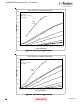
(i.e. from 1:2 to 1:4) provides a lower slope, but,
more precise response curve. This same in-
crease in ratio, however, will reduce flow capac-
ity and should be considered when selecting the
proper regulator ratio.
The following factors must then be considered
when selecting the regulator ratio required for
proper fluid control:
• Maximum fluid output requirements (Guide:
10 psi minimum, 30 psi max.)
• Fluid tubing inside diameter (ID) and length
• Fluid feed tube inside diameter (ID) and length
• Fluid viscosity
• Fluid input pressures (Guide: 10 psi above
max. fluid output pressure)
Only proper testing will determine which regula-
tor ratio should be used. If conditions change
after installation which require a different low
flow ratio, this regulator can be altered easily by
replacing the existing ratio spacer ring and up-
per retainer with the desired ratio (ratio designa-
tion is etched on the side of the spacer ring).
The output of the regulator is externally con-
nected to a fitting on the fluid manifold assem-
bly. The fluid manifold assembly is equipped
with valves which are pneumatically operated to
direct the flow of paint to either the feed tube or
dump line and to supply a intermittent solvent
bell wash for the feed tube and bell cup.
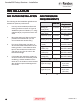
The feed tube is available in several sizes (See
Figure 11). The viscosity and volume of the
coating material being sprayed determine the
correct size of feed tube for each installation.
The feed tube diameter acts as a linear
restrictor to create back pressure on the fluid
regulator so that it can provide accurate and re-
peatable flow to air signal resolution.
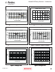
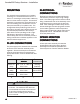
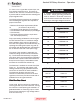
Figure 10: Fluid Regulator SelectionsFigure 10: Fluid Regulator Selections
Figure 10: Fluid Regulator SelectionsFigure 10: Fluid Regulator Selections
Figure 10: Fluid Regulator Selections
Low Flow RatesLow Flow Rates
Low Flow RatesLow Flow Rates
Low Flow Rates
1:1
1:2
1:3
1:4
1:6
1:8
1:10
Fixed AtomizerFixed Atomizer
Fixed AtomizerFixed Atomizer
Fixed Atomizer
Regulator Part No.Regulator Part No.
Regulator Part No.Regulator Part No.
Regulator Part No.
LREG5001-01
LREG5001-02
LREG5001-03
LREG5001-04
LREG5001-06
LREG5001-08
LREG5001-10
Fluid Flow Rate Check:Fluid Flow Rate Check:
Fluid Flow Rate Check:Fluid Flow Rate Check:
Fluid Flow Rate Check:
In test mode, the flow rate can be measured by
removing the bell cup from the atomizer, turning
the fluid flow on and capturing the material in a
graduated beaker or measuring cup for a fixed
period of time (shaping air, high voltage and tur-
bine air must be off).
> Danger of shock and/or personal injury
can occur. Proper grounding procedures
must be followed. Personnel must never
work around the turbine when the turbine is
spinning or when high voltage is turned on.
W A R N I N GW A R N I N G
W A R N I N GW A R N I N G
W A R N I N G
!!
!!
!
1515
1515
15
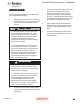
Figure 11: Fluid Tube SelectionsFigure 11: Fluid Tube Selections
Figure 11: Fluid Tube SelectionsFigure 11: Fluid Tube Selections
Figure 11: Fluid Tube Selections
Orifice SizeOrifice Size
Orifice SizeOrifice Size
Orifice Size
.041 I.D.
.061 I.D.
.093 I.D.
.125 I.D.
Part No.Part No.
Part No.Part No.
Part No.
77971-04
77971-06
77971-09
77971-13