
Install Guide


Pg. 7
SM-PROJ-XL Installation Manual
www.snapav.com Support: 866.838.5052
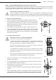
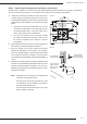
Center of Balance
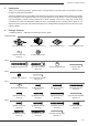
(D)x4
(F)x4
Projection Screen
Point arrows on
mounting base (C)
toward screen
Afterthecenterofbalanceisfound,themountingbaseassemblymustbeattachedtotheprojector.Attachment
willvaryforalmosteveryprojector,sothepositionofthearmscanbere-conguredasneeded.
Step 5. Attaching the Mounting Base Assembly to the Projector
A. Loosenthefourbolts(F)holdingthearms(D)inplace
to allow enough movement for alignment, then lay the
mountingbaseassemblyoverthecenter-of-gravitymark
on the projector and position the arms over the mounting
points.
I. Ifthearmswillnotreachalltheholes,theycanbe
movedandre-attachedinanyoftheotherslotson
themounting baseplate. If a projector has only 3
holes,simplyremovetheun-neededarm.
II. If an arm is protruding too far out (where it would
be visible from below the projector), that arm can
be moved to a different slot to allow for a cleaner
arrangement.
B. Aftertheideallocationforthearmsisfound,tightenthe
armscrews(F)usinga#2Phillipsscrewdriver.
C. Parts (K) through (X) are the screws and washers
included for attachment of the mount to the projector.
There are several lengths in each thread size included
forusewiththespacers(I)ifneeded.Testthescrews
in the projector mounting holes until the thread pattern is
found.
D. Attachthemountingassemblyusingthelongestscrews
with the correct thread pitch that will not bottom out in the
projector, but will still tighten completely. Use up to two
spacers(I)betweeneacharmandtheprojectortoclear
protrusions if needed.
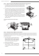
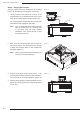
Note: SeeFigure9foranexampleoftheattachment
of the arm to the projector body.
IftheM3orM4(LthroughQ)screwsareused
for attachment, use the washers (K) between
the screw head and the arms.
IftheM5orM6screws(RthroughX)areused
thennowasherisrequired.
Figure 8
Figure 9
Use spacers (I) to
adjust clearance
between mount
and projector
M5 and M6 Bolts
(R through X)
Use Washer (K)
with M3 and M4
Bolts (L through Q)